
User guide

Spartan-6 FPGA Configuration User Guide www.xilinx.com 81
UG380 (v2.7) October 29, 2014
Configuration Sequence
Setup (Steps 1-3)
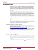
The setup process is similar for all configuration modes (see Figure 5-3).
The setup steps are critical for proper device configuration. The steps include Device
Power-Up, Clear Configuration Memory, and Sample Mode Pins.
Device Power-Up (Step 1)
For configuration, Spartan-6 devices require power on the VCCO_2, V
CCAUX
, and V
CCINT
pins. There are no power-supply sequencing requirements. Power V
CCO
last after V
CCINT
and V
CCAUX
to ensure that the outputs stay disabled until configuration begins.
All JTAG and serial configuration pins are located in V
CCAUX
and VCCO_2 supply banks.
The dual-purpose pins are located in Banks 0, 1, and 2 (one exception is A24 and A25 are in
bank 5 for larger devices with 6 I/O banks). The DONE and PROGRAM_B dedicated
inputs operate at the VCCO_2 LVCMOS level, and the JTAG input pins (TCK, TMS, and
TDI) and the SUSPEND pin operate at the V
CCAUX
LVCMOS level. The DONE pin
operates at the VCCO_2 voltage level with the output standard set to LVCMOS 8 mA
SLOW. TDO drives at the voltage level provided on V
CCAUX
at 8 mA SLOW.
For all modes that use dual-purpose I/O, the associated VCCO_X must be connected to the
appropriate voltage to match the I/O standard of the configuration device. The pins are
also LVCMOS18, LVCMOS25, or LVCMOS33 8 mA SLOW during configuration,
depending on the VCCO_X level.
For power-up, the V
CCINT
power pins must be supplied with 1.2V for -2/-3 speed grades
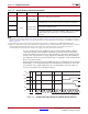
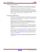
and 1.0V for -1L sources. VCCO_2 must be supplied. Table 5-11 shows the power supplies
required for configuration. Table 5-12 shows the timing for power-up.
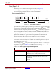
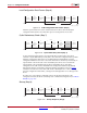
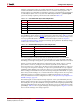
X-Ref Target - Figure 5-3
Figure 5-3: Device Power-Up (Step 1)
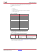
Table 5-11: Power Supplies Required for Configuration
Pin Name
(1)
Description
V
CCINT
Internal core voltage.
V
BATT
(2)
Encryption Key battery supply. If there is no encryption key
being stored in the volatile memory, V
BATT
should be
connected to V
CCAUX
or GND, or left unconnected.
V
FS
Encryption Key eFUSE programming voltage. If eFUSE
programming is not needed, connect V
FS
to V
CC
or GND
(recommended).
V
CCAUX
(3)
Auxiliary power input for configuration logic and other FPGA
functions.
Device
Power-Up
Sample Mode
Pins
Synchronization
Device ID
Check
CRC Check
Clear
Configuration
Memory
Startup
Sequence
Load
Configuration
Data
Start
Finish
UG380_c5_03_042909
Bitstream
Loading
Steps
123 45678
Setup