
User guide

Spartan-6 FPGA Configuration User Guide www.xilinx.com 79
UG380 (v2.7) October 29, 2014
Generating PROM Files
Parallel Bus Bit Order
Traditionally, in SelectMAP x8 mode, configuration data is loaded one byte per CCLK,
with the most-significant bit (MSB) of each byte presented to the D0 pin. Although this
convention (D0 = MSB, D7 = LSB) differs from many other devices, it is consistent across all
Xilinx FPGAs. The bit-swap rule also applies to Spartan-6 FPGA BPI x8 modes (see Bit
Swapping, page 78).
In Spartan-6 devices, the bit-swap rule is extended to x16 bus widths; the data is bit
swapped within each byte.
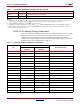
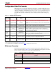
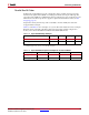
Table 5-8 and Table 5-9 show examples of a sync word inside a bitstream. These examples
illustrate what is expected at the FPGA data pins when using parallel configuration
modes, such as Slave SelectMAP and Master SelectMAP (BPI) modes.
Table 5-8: Sync Word Bit Swap Example
Sync Word [31:24]
(1)
[23:16] [15:8] [7:0]
Bitstream Format 0xAA 0x99 0x55 0x66
Bit Swapped 0x55 0x99 0xAA 0x66
Notes:
1. [31:24] changes from 0xAA to 0x55 after bit swapping.
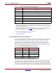
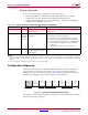
Table 5-9: Sync Word Data Sequence Example for x8 and x16 Modes
CCLK Cycle 1 2 3 4
D[7:0] pins for x8 0x55 0x99 0xAA 0x66
D[15:0] pins for x16 0x5599 0xAA66