
User guide

Spartan-6 FPGA Configuration User Guide www.xilinx.com 73
UG380 (v2.7) October 29, 2014
Configuration Pins
Floating signal levels are problematic in CMOS logic systems. Other logic components in
the system can require a valid input level from the FPGA. The internal pull-up resistors
generate a logic High level on each pin. Generally, a device driving signals into the FPGA
can overcome the pull-up resistor. Similarly, an individual pin can be pulled down using
an appropriately sized external pull-down resistor.
In hot-swap or hot-insertion applications, the pull-up resistors provide a potential current
path to the I/O power rail. Turning off the pull-up resistors disables this potential path.
However, then external pull-up or pull-down resistors can be required on each individual
I/O pin.
During power-up or at reconfiguration following PROG_B assertion, the I/O pull-ups may
be enabled until the device begins configuration.
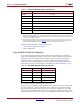
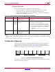
Reserving Dual-Purpose Configuration Pins (Persist)
Dual-purpose pins serve as configuration pins and user I/Os after configuration. The
BitGen option -g Persist is used to reserve these pins as configuration pins (see
Table 5-3 for the settings).
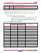
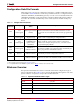
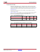
FWE_B Pull-up to VCCO_1 No termination User I/O
MOSI/CSI_B Pull-up to VCCO_2 No termination User I/O
RDWR_B Pull-up to VCCO_2 No termination User I/O
AWAKE Pull-up to VCCO_1 No termination User I/O if Suspend feature is not used
(4)
SUSPEND No termination No termination SUSPEND pin
(3)(4)
HDC Pull-up to VCCO_1 No termination User I/O
LDC Pull-up to VCCO_1 No termination User I/O
USERCCLK Pull-up to VCCO_2 No termination User I/O
Other I/O
(not used during
configuration)
Pull-up to VCCO No termination User I/O
Notes:
1. A24/A25 are in bank 5 in the 6SLX75/T devices and larger densities and in FG676 and larger packages. Then the pull-up is to
VCCO_5.
2. Setting the BitGen options configures the termination on the respective pin. Not setting an option defaults to Pull-up. Refer to the
BitGen section of UG628
, Command Line Tools User Guide, for software settings.
3. The SUSPEND pin must be Low during power-up. Connection of an external pull-down resistor ensures this condition.
4. For more details on the Suspend feature, refer to UG394
, Spartan-6 FPGA Power Management User Guide.
Table 5-2: Spartan-6 FPGA Configuration Pin Termination (Cont’d)
Pin
Pre-Configuration
Post-Configuration
HSWAPEN = 0
(enabled)
HSWAPEN = 1
(disabled)
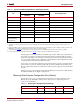
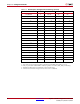
Table 5-3: Dual-Purpose Configuration Pin Settings
Pin Name Bank SelectMAP BPI SPI/Serial
DIN/D0/MISO/MISO[1] 2 Persist No Persist
D1/MISO2 2 Persist No No