
User guide

62 www.xilinx.com Spartan-6 FPGA Configuration User Guide
UG380 (v2.7) October 29, 2014
Chapter 3: Boundary-Scan and JTAG Configuration
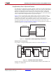
The devices in the JTAG chain are configured one at a time. The multiple device
configuration steps can be applied to any size chain as long as an excellent signal integrity
is maintained. The iMPACT software automatically discovers the devices in the chain,
starting from the one nearest to TDI coming from the JTAG header and the iMPACT
software.
JTAG inputs use the V
CCAUX
supply for JTAG operations.
Chapter 10, Advanced JTAG Configurations provides a detailed description of the various
TAP controller states, the JTAG instructions, and the architecture of the boundary-scan
chain.
For details on the boundary-scan instructions EXTEST, INTEST, and BYPASS, refer to the
IEEE Std 1149.1 and Chapter 10, Advanced JTAG Configurations.
For further information on the startup sequence, bitstream, and internal configuration
registers referenced here, refer to Chapter 5, Configuration Details and Chapter 10,
Advanced JTAG Configurations.
Design Considerations
JTAG Signal Routing
The TCK and TMS signals go to all devices in the chain; consequently, their signal quality
is important. For example, TCK should transition monotonically at all receivers to ensure
proper JTAG functionality and must be properly terminated. The quality of TCK can limit
the maximum frequency for reliable JTAG configuration.
Additionally, if the chain is large (three devices or more), TMS and TCK should be buffered
to ensure that they have sufficient drive strength at all receivers, and the voltage at logic
High must be compatible with all devices in the chain.
When interfacing to devices from other manufacturers, optional JTAG signals can be
present (such as TRST and enables) and might need to be driven.
Providing Power
To ensure proper power-on behavior, the guidelines in the Spartan-6 FPGA Data Sheet: DC
and Switching Characteristics must be followed. The power supplies should ramp
monotonically within the power supply ramp time range specified. All supply voltages
should be within the recommended operating ranges; any dips in V
CCINT
below V
DRINT
or
V
CCAUX
below V
DRAUX
can result in loss of configuration data.
VCCO_2 and sometimes VCCO_1
determine the I/O voltage for the configuration
interface (SPI, Serial, BPI, and SelectMAP). V
CCAUX
determines the I/O voltage for the
JTAG configuration pins. The voltage provided must be compatible with all configuration
interfaces that will be used
Unused serial transceivers have no effect on boundary-scan functionality and need not be
powered.