
User guide


Spartan-6 FPGA Configuration User Guide www.xilinx.com 61
UG380 (v2.7) October 29, 2014
Boundary-Scan for Spartan-6 Devices Using IEEE Std 1149.1
Using Boundary-Scan in Spartan-6 Devices
For single-device configuration, the TAP controller commands are issued automatically if
the part is being configured with Xilinx® iMPACT software. The download cable must be
attached to the appropriate four JTAG pins (TMS, TCK, TDI, and TDO) to deliver the
bitstream automatically from the computer port to the Spartan-6 FPGA. The iMPACT
software automatically checks for proper connections and drives the commands to deliver
and/or verify that the configuration bits are properly managed.
Figure 3-2 shows a typical JTAG setup with the simple connection required to attach a
single device to a JTAG signal header, which can be driven from a processor or a Xilinx
programming cable under control of iMPACT software. TCK is the clock used for
boundary-scan operations. The TDO-TDI connections create a serial datapath for shifting
data through the JTAG chain. TMS controls the transition between states in the TAP
controller; see Chapter 10, Advanced JTAG Configurations. Proper physical connections of
all of these signals are essential to JTAG functionality.
Multiple Device Configuration
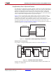
It is possible to configure multiple Spartan-6 devices in a chain. (See Figure 3-3.)
If JTAG is the only configuration mode, then PROGRAM_B, INIT_B, and DONE can be
tied High to a 330Ω resistor.
X-Ref Target - Figure 3-2
Figure 3-2: Single-Device JTAG Programming Connections
X-Ref Target - Figure 3-3
Figure 3-3: Boundary-Scan Chain of Devices
TDO
TCK
TMS
TDI
TDO
TCK
TMS
TDI
Spartan-6
FPGA
Device
JTAG Header
UG380_c3_02_042909
JTAG Header
UG380_c3_03_042909
Spartan-6
FPGA
TDOTDI
TMS
TCK
Spartan-6
FPGA
PROGRAM_B
TDI
TMS
TCK
PROGRAM_B
TDO
Spartan-6
FPGA
TDI
TMS
TCK
PROGRAM_B
TDO
Device 0 Device 1 Device 2
TDO
TMS
TDI
TCK