
User guide

60 www.xilinx.com Spartan-6 FPGA Configuration User Guide
UG380 (v2.7) October 29, 2014
Chapter 3: Boundary-Scan and JTAG Configuration
The four mandatory TAP pins are outlined in Table 3-1.
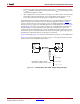
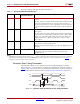
Boundary-Scan Timing Parameters
Characterization data for some of the most commonly requested timing parameters,
shown in Figure 3-1, are listed in the “Configuration Switching Characteristics” table of
DS162
, Spartan-6 FPGA Data Sheet: DC and Switching Characteristics. For more information
on the configuration flow details, refer to Chapter 10, Advanced JTAG Configurations.
Table 3-1: Spartan-6 FPGA TAP Controller Pins
Pin Direction
Pre-Configuration
Internal Pull Resistor
Description
TDI IN Pull-up
(1)
Test D a ta In. This pin is the serial input to all JTAG instruction and data
registers.
The state of the TAP controller and the current instruction determine the
register that is fed by the TDI pin for a specific operation. TDI has an
internal resistive pull-up to provide a logic High to the system if the pin
is not driven. TDI is applied into the JTAG registers on the rising edge of
TCK.
TDO
Out Pull-up
(1)
Test Data Out. This pin is the serial output for all JTAG instruction and
data registers.
The state of the TAP controller and the current instruction determine the
register (instruction or data) that feeds TDO for a specific operation. TDO
changes state on the falling edge of TCK and is only active during the
shifting of instructions or data through the device. TDO is an active
driver output.
TMS
In Pull-up
(1)
Test Mode Select. This pin determines the sequence of states through the
TAP controller on the rising edge of TCK.
TMS has an internal resistive pull-up to provide a logic High if the pin is
not driven.
TCK
In Pull-up
(1)
Test C l o ck. This pin is the JTAG Test Clock.
TCK sequences the TAP controller and the JTAG registers in the
Spartan-6 devices.
Notes:
1. All JTAG pins have internal pull-up resistors to V
CCAUX
before configuration. These internal pull-up resistors are active, regardless
of the mode selected. BitGen can be used to enable the pull-ups after configuration for all four mandatory pins. See UG628,
Command Line Tools User Guide for more information.
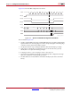
X-Ref Target - Figure 3-1
Figure 3-1: Spartan-6 FPGA Boundary-Scan Port Timing Waveforms
UG380_c3_01_042909
TDO
TCK
TDI
TMS
Data Valid
T
TCKTDO
T
TAPTCK
T
TCKTAP