
User guide


52 www.xilinx.com Spartan-6 FPGA Configuration User Guide
UG380 (v2.7) October 29, 2014
Chapter 2: Configuration Interface Basics
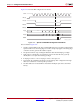
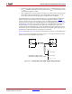
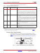
Figure 2-21 shows the BPI configuration waveforms.
Notes related to Figure 2-21:
1. CCLK is output in BPI modes. The parallel NOR flash does not require CCLK, but the
Spartan-6 FPGA uses the rising edge of CCLK to sample D[n:0] pins. The falling edge
of CCLK is used to generate the address outputs.
2. The Spartan-6 FPGA stops loading the bitstream after the DONE pin goes High.
3. Dual-purpose configuration I/O switches to User mode after the GTS_cycle. By
default, this is one cycle after DONE goes High.
4. In D[n:0], n can be 7 or 15. For A[n:0], n can be a value up to 25.
5. FCS_B, FOE_B, and FWE_B should have weak pull-ups after configuration through
either I/O constraints or external pull-up resistors.
6. The first address 0 for Master BPI is extended for multiple cycles due to the initial
latency.
X-Ref Target - Figure 2-21
Figure 2-21: Spartan-6 FPGA BPI Configuration Waveforms
10
CCLK
INIT_B
FCS_B
FOE_B
FWE_B
A[n:0]
D[n:0]
DONE
2 3 n
DnD3D2D1D0
UG380_c2_20_052109