
User guide

Spartan-6 FPGA Configuration User Guide www.xilinx.com 51
UG380 (v2.7) October 29, 2014
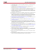
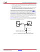
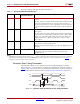
Master BPI Configuration Interface
6. A24 and A25 can be in I/O bank 5, depending on the device. Consult the pinout for
your selected device.
7. Sending a bitstream to the data pin follows the same bit-swapping rule as in
SelectMAP mode. See Parallel Bus Bit Order, page 79.
8. If flash programming is not required, FCS_B, FOE_B, and FWE_B can be tied off; that
is, DONE is connected to FCS_B, FOE_B is tied Low, and FWE_B is tied High.
9. The CCLK outputs are not used to connect to flash but are used to sample flash read
data during configuration. All timings are referenced to CCLK. The CCLK pin must
not be driven or tied High or Low.
10. If HSWAPEN is left unconnected or tied High, a pull-up resistor is required for FCS_B.
11. The DONE pin is by default an open-drain output with an internal pull-up. An
additional external pull-up is recommended in general, but required when using the
indirect programming method using iMPACT. The DONE pin has a programmable
active driver that can be enabled via the BitGen option -g DriveDone.
12. Required Data Spacing between MultiBoot Images, page 136 provides information on
when the DCM or PLL lock wait is turned on.
13. For details on how to daisy-chain FPGAs in BPI mode, see Chapter 9, Advanced
Configuration Interfaces.
14. The parallel NOR flash vendor data sheet should be referred to for details on the
specific flash signal connectivity. To prevent address misalignment, close attention
should be paid to the flash family address LSB for the byte/word mode used. Not all
flash families use the A0 as the address LSB.
15. The CCLK frequency is adjusted by using the BitGen option ConfigRate if the source
is the internal oscillator. If an external clock source is used, see External Configuration
Clock for Master Modes, page 54.
16. V
FS
is present in 6SLX75/T, 6SLX100/T, and 6SLX150/T devices, and is used for
eFUSE programming. See eFUSE, page 91 for more details.
17. V
BATT
is present in 6SLX75/T, 6SLX100/T, and 6SLX150/T devices, and is the power
source for AES key storage. If AES encryption is unused, V
BATT
can be tied to either
V
CCAUX
or ground, or left unconnected.
18. If VCCO_2 is 1.8V, V
CCAUX
must be 2.5V. If VCCO_2 is 2.5V or 3.3V, V
CCAUX
can be
either 2.5V or 3.3V.
19. The SUSPEND pin should be Low during power up and configuration. If the Suspend
feature is not used, the SUSPEND pin must be connected to ground.