
User guide

50 www.xilinx.com Spartan-6 FPGA Configuration User Guide
UG380 (v2.7) October 29, 2014
Chapter 2: Configuration Interface Basics
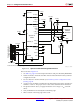
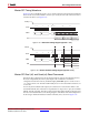
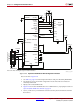
Notes relevant to Figure 2-20:
1. See Table 5-2, page 72 for internal pin terminations and pins affected by HSWAPEN.
2. The CCLK net is not used in this configuration mode and can be unconnected or
externally terminated.
3. M[1:0] = 00 for Master BPI mode.
4. Figure 2-20 shows the x16 BPI interface. For x8 BPI interfaces, only D[7:0] are used. See
Sync Word/Bus Width Auto Detection, page 76.
5. VCCO_1 and VCCO_2 should be the same because they both communicate with the
flash device.
X-Ref Target - Figure 2-20
Figure 2-20: Spartan-6 FPGA Master BPI Configuration Interface
UG380_c2_20_052914
TMS
TDO
TCK
TDI
VCCINT
VCCAUX
FWE_B
CCLK
CSO_B
INIT_B
FOE_B
FCS_B
PROGRAM_B
DONE
VCCO_2
CE#
WE#
VCCO
OE#
M1
M0
VCCO_0
VCCO_1
VCCO_0
VCCO_1
x8/x16
Parallel NOR
Flash
DOUT/BUSY
HDC
LDC
VCCO_2
GND
GND
A[25:0]
D[15:8]
BYTE#
D [15:8]
PROGRAM_B
1
14
Xilinx Cable Header
(JTAG Interface)
VREF
TMS
TCK
TDO
TDI
N.C.
N.C.
A[n:0]
D[7:0]D[7:0]
Spartan-6 FPGA
HSWAPEN
VCCAUX
VCCO_1
VCCO_2
VCCO_2
VCCAUX
VCCO_1
4.7 kΩ
4.7 kΩ
4.7 kΩ
4.7 kΩ
330Ω
4.7 kΩ
Refer to the Notes following this figure for related information.
VFS
VBATT
VFS
VBATT
SUSPEND