
User guide

Spartan-6 FPGA Configuration User Guide www.xilinx.com 49
UG380 (v2.7) October 29, 2014
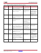
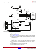
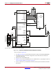
Master BPI Configuration Interface
DONE Bidirectional,
Open-Drain,
or Active
Dedicated Active-High signal indicating configuration is complete:
0 = FPGA not configured
1 = FPGA configured
INIT_B Input or
Output,
Open-Drain
Dual-
Purpose
Before the Mode pins are sampled, INIT_B is an input that can be held
Low to delay configuration. After the Mode pins are sampled, INIT_B
is an open-drain, active-Low output indicating whether a CRC error
occurred during configuration:
0 = CRC error
1 = No CRC error
When the SEU detection function is enabled, INIT_B is reserved and
cannot be used as user I/O.
PROGRAM_B Input Dedicated Active-Low asynchronous full-chip reset
CCLK Output Dual-
Purpose
Configuration clock output. CCLK does not directly connect to parallel
NOR flash but is used internally to generate the address and sample
read data.
FCS_B Output Dual-
Purpose
Active-Low flash chip select output. This output is actively driven Low
during configuration and 3-stated after configuration. It has a weak
pull-up resistor during configuration. By default, this signal has a weak
pull-down resistor after configuration.
FOE_B Output Dual-
Purpose
Active-Low flash output enable. This output is actively driven Low
during configuration and 3-stated after configuration. It has a weak
pull-up resistor during configuration. By default, this signal has a weak
pull-down resistor after configuration.
FWE_B Output Dual-
Purpose
Active-Low flash write enable. This output is actively driven High
during configuration and 3-stated after configuration. It has a weak
pull-up resistor during configuration. By default, this signal has a weak
pull-down resistor after configuration.
A[25:0] Output Dual-
Purpose
Address output, generated on the falling edge of CCLK.
D[15:0] Input Dual-
Purpose
Data input, sampled by the rising edge of the FPGA CCLK.
CSO_B Output Dual-
Purpose
Parallel daisy-chain active-Low chip select output. Not used in single
FPGA applications.
HDC Output Dual-
Purpose
High During Configuration (HDC) is High and can be connected to the
flash device to control byte-wide output versus 16-bit output.
LDC Output Dual-
Purpose
Low During Configuration (LDC) is Low and can be connected to the
flash device to control byte-wide output versus 16-bit output.
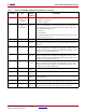
Table 2-7: Spartan-6 FPGA BPI Configuration Interface Pins (Cont’d)
Pin Name Type
Dedicated
or Dual-
Purpose
Description