
User guide

48 www.xilinx.com Spartan-6 FPGA Configuration User Guide
UG380 (v2.7) October 29, 2014
Chapter 2: Configuration Interface Basics
through the Spartan-6 device to the flash device. For a list of supported BPI devices, refer
to the ISE software overview at
http://www.xilinx.com/support/documentation/sw_manuals/xilinx11/isehelp_start.htm and
navigate to the iMPACT help section “Introduction to Indirect Programming – SPI or BPI
Flash Memory.”
For more details see X
APP973, Indirect Programming of BPI PROMs with Virtex-5 FPGAs.
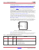
The FPGA drives up to 26 address lines to access the attached parallel flash. For
configuration, only async read mode is used, where the FPGA drives the address bus, and
the flash PROM drives back the bitstream data. Bus widths of x8 and x16 are supported. If
the parallel NOR flash supports both x8 and x16 data widths, it is necessary to tie the
BYTE# signal to the appropriate level for the desired width. Bus widths are auto detected,
as described in Sync Word/Bus Width Auto Detection, page 76.
In Master BPI mode when using a parallel NOR flash device, the CCLK output is not
connected to the parallel NOR flash device. However, flash data is still sampled on the
rising edge of CCLK. The address output is generated on the falling edge of CCLK. See
Board Layout for Configuration Clock (CCLK), page 54. The timing parameters related to
BPI use CCLK as a reference.
In Master BPI mode, the address starts at 0 and increments by 1 until the DONE pin is
asserted. If the address reaches the maximum value (26’h3FFFFFF) and configuration is
not done (DONE is not asserted), the counter wraps around and starts again from 0.
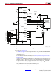
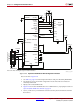
Table 2-7 defines the BPI configuration interface pins.
If the FPGA is subject to reprogramming during configuration from the parallel NOR flash,
then the INIT pin can be connected to the BPI reset to set the BPI into a known state.
X-Ref Target - Figure 2-19
Figure 2-19: Spartan-6 FPGA BPI Configuration Interface
UG380_c2_25_121109
HSWAPEN
INIT_B
D[15:0]
M[1:0]
PROGRAM_B
CCLK
A[25:0]
CSO_B
DONE
FWE_B
FCS_B
FOE_B
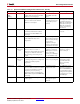
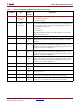
Table 2-7: Spartan-6 FPGA BPI Configuration Interface Pins
Pin Name Type
Dedicated
or Dual-
Purpose
Description
M[1:0] Input Dual-
Purpose
The Mode pins are set to 00 for Master BPI mode when configuring
with parallel NOR flash:
00 = Master BPI mode
HSWAPEN Input Dual-
Purpose
Controls I/O pull-up resistors during configuration. This pin has a
built-in weak pull-up resistor.
0 = Pull-up during configuration
1 = 3-state during configuration