
User guide
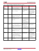

Spartan-6 FPGA Configuration User Guide www.xilinx.com 45
UG380 (v2.7) October 29, 2014
SPI Configuration Interface
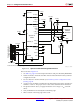
Master SPI Timing Waveform
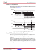
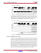
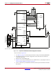
Figure 2-15 shows SPI Read (opcode = 03H), which is the first read command issued by the
device. If this read command fails to return a sync word, the next read command of E8h is
issued to the device (see Figure 2-16).
Master SPI Dual (x2) and Quad (x4) Read Commands
The Master SPI configuration mode in Spartan-6 FPGAs supports the SPI flash memory
dual (x2) and quad bit (x4) memory fast output read commands. To enable this
configuration method in software, the BitGen spi_buswidth option is used to create a
.bit file for SPI x2 or x4. The FPGA still initially boots in x1 mode and then switches to x2
or x4 mode.
In x2 mode, the Fast-Read Dual Output (3Bh) instruction is issued and is similar to the
standard Fast Read (0Bh) instruction except that data is output on two pins, DO and DIO
(MOSI), instead of just DO. This allows data to be transferred from the dual output at twice
the rate of standard SPI devices. The timing diagram of the Master Serial SPI configuration
mode using an SPI flash with dual read-bit command (3Bh) is shown in Figure 2-17.
X-Ref Target - Figure 2-15
Figure 2-15: Master SPI Timing Diagram (opcode = 03h)
X-Ref Target - Figure 2-16
Figure 2-16: Master Serial SPI Timing Diagram (opcode = E8h)
MOSI
DIN
CCLK
OPCODE 03H
102 7 12 29 3947
30
31
Address Bits A23-A0
Data Byte 2Data Byte 1 Data Byte 3
UG380_c2_15_052009
CSO_B
CSO_B
MOSI
DIN
CCLK
OPCODE E8H
12 7 12 29 63 71
30
31
Address Bits A23-A0 32 Dummy Cycles
Data Byte 1 Data Byte 2
UG380_c2_16_052009