
User guide

44 www.xilinx.com Spartan-6 FPGA Configuration User Guide
UG380 (v2.7) October 29, 2014
Chapter 2: Configuration Interface Basics
complete list, see the URL for the ISE software overview at the beginning of SPI
Configuration Interface, page 40.
2. Software support for x4 requires the x4 capability enabled in BitGen
(-g: spi_buswidth:4).
3. The SPI device needs to be programmed with a specific register setting, which is done
in iMPACT software, to enable x4 output.
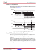
4. Figure 2-12 is used as a basis for the connections for x4 data width mode. The only
differences are the MISO[2] and MISO[3] connections. These two pins also require
pull-ups to VCCO_2.
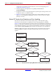
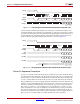
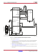
Master SPI Vendor Auto-Detection and Error Handling
The SPI read command is automatically selected, using a read-command looping
mechanism for the initial device configuration. This looping algorithm is outlined in
Figure 2-14. SPI x2 and x4 applications use this sequence for an initial data load. After the
first set of commands are issued to the FPGA, the read command changes in the Mode_Reg
and configuration changes to x2 or x4 mode using the IPROG command. To enable these
modes, the BitGen spi_buswidth option needs to have the SPI x2 or x4 command set.
MultiBoot applications require a manual setting of the read command to be used along
with other MultiBoot settings contained in the Mode_Reg, General 2, and General 4
registers.
X-Ref Target - Figure 2-14
Figure 2-14: Read-Command Looping Mechanism during Initial Configuration
Master Serial Mode
Set Error Count =
0
Initiate SPI with
OPCODE 0x03,
Address =
0
Sync Word in 512 Cycles?
CRC Error?
Config Passes,
Startup Sequence
Configure Device
Initiate SPI with
OPCODE 0xE8
Address = 0
No
Ye s
Ye s
Ye s
Ye s
No
No
No
Sync Word in 512 Cycles?
Increment Error
Count
Error Count
< 3?
Fail Configuration,
Init =
0
UG380_c2_14_011310