
User guide

Spartan-6 FPGA Configuration User Guide www.xilinx.com 43
UG380 (v2.7) October 29, 2014
SPI Configuration Interface
8. There are additional pins on the SPI flash side, such as Write Protect and Hold. These
pins are not used in FPGA configuration (read only). But they should be tied off
appropriately according to the SPI vendor’s specification.
9. If HSWAPEN is left unconnected or tied High, a pull-up resistor is required for CSO_B.
10. The CCLK frequency is adjusted by using the BitGen option ConfigRate if the source
is the internal oscillator. If an external source is used, see External Configuration Clock
for Master Modes, page 54 for more details.
11. The DONE pin is by default an open-drain output with an internal pull-up. An
additional external pull-up is recommended in general, but required when using the
indirect programming method using iMPACT. The DONE pin has a programmable
active driver that can be enabled via the BitGen option -g DriveDone.
12. When the digital clock manager (DCM) or PLL lock wait is enabled before the DONE
release cycle during startup, the FPGA continues to clock in data until the startup wait
condition is met and DONE is released. See Required Data Spacing between MultiBoot
Images, page 136 for considerations specific to MultiBoot Configuration.
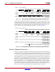
13. Figure 2-12 shows a Numonyx SPI flash device. Refer to the ISE software overview at
http://www.xilinx.com/support/documentation/sw_manuals/xilinx11/isehelp_start.htm
and navigate to the iMPACT help documentation (“Introduction to Indirect
Programming”) to see which devices are supported for indirect SPI configuration
using iMPACT.
14. V
FS
is present in 6SLX75/T, 6SLX100/T, and 6SLX150/T devices, and is used for
eFUSE programming. See eFUSE, page 91 for more details.
15. V
BATT
is present in 6SLX75/T, 6SLX100/T, and 6SLX150/T devices, and is the power
source for AES key storage. If AES encryption is unused, V
BATT
can be tied to either
V
CCAUX
or ground, or left unconnected.
16. If VCCO_2 is 1.8V, V
CCAUX
must be 2.5V. If VCCO_2 is 2.5V or 3.3V, V
CCAUX
can be
either 2.5V or 3.3V.
17. The SUSPEND pin should be Low during power up and configuration. If the Suspend
feature is not used, the SUSPEND pin must be connected to ground.
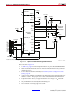
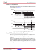
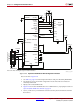
Spartan-6 FPGAs also support x4 configuration with SPI PROMs in Master Serial Mode.
See Figure 2-13.
Notes relevant to Figure 2-13:
1. The connection shown in Figure 2-13 uses the Winbond W25Q SPI series flash PROM.
Other SPI devices are supported, including devices from Spansion and Micron. For a
X-Ref Target - Figure 2-13
Figure 2-13: Master Serial Quad-Bit SPI Configuration
UG380_c2_13_052009
CLKCCLK
CS
DO (bit1)
WP (bit2)
HOLD (bit3)
MOSI/MISO[0]
CSO_B
DIN/D0/MISO/MISO[1]
MISO[2]
MISO[3]
Winbond
W25Q SPI
Spartan-6
Device
DI (bit0)