
User guide

38 www.xilinx.com Spartan-6 FPGA Configuration User Guide
UG380 (v2.7) October 29, 2014
Chapter 2: Configuration Interface Basics
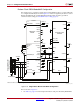
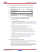
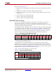
Notes relevant to Figure 2-9:
1. RDWR_B is driven Low by the user, setting the D[0:n] pins as inputs for configuration.
RDWR_B can be tied Low if readback is not needed. RDWR_B should not be toggled
after CSI_B has been asserted because this triggers an ABORT. See SelectMAP ABORT,
page 153. CSI_B cannot be deasserted during the sync word.
2. The device is ready for configuration after INIT_B toggles High.
3. The user asserts CSI_B Low, enabling the SelectMAP data bus. CSI_B signal can be tied
Low if there is only one device on the SelectMAP bus. If CSI_B is not tied Low, it can be
asserted at any time.
4. A byte is loaded on the rising CCLK edge. The data bus can be x8 or x16 wide.
5. A byte is loaded on the rising CCLK edge.
6. The user deasserts CSI_B, and the byte is ignored.
7. The user deasserts CSI_B, and the byte is ignored.
8. A byte is loaded on the rising CCLK edge.
9. A byte is loaded on the rising CCLK edge.
10. The user deasserts CSI_B, and the byte is ignored.
11. A byte is loaded on the rising CCLK edge.
12. A byte is loaded on the rising CCLK edge.
13. A byte is loaded on the rising CCLK edge.
X-Ref Target - Figure 2-9
Figure 2-9: Non-Continuous SelectMAP Data Loading with Free-Running CCLK
PROGRAM_B
INIT_B
CCLK
CSI_B
RDWR_B
DATA[0:n]
UG380_c2_09_042909
(2)
(4) (5) (6) (7) (8) (9) (10) (11) (12) (13)
(1)
(3)
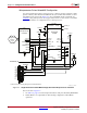
X-Ref Target - Figure 2-10
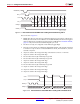
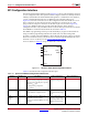
Figure 2-10: Non-Continuous SelectMAP Data Loading with Controlled CCLK
CCLK
CSI_B
RDWR_B
DATA[0:n]
UG380_c2_10_042909
Byte 0 Byte 1 Byte n
(1)
(2)
(3)
(4) (5) (6)