
User guide

36 www.xilinx.com Spartan-6 FPGA Configuration User Guide
UG380 (v2.7) October 29, 2014
Chapter 2: Configuration Interface Basics
RDWR_B
RDWR_B is an input to the Spartan-6 device that controls whether the data pins are inputs
or outputs:
•If RDWR_B = 0, the data pins are inputs (writing to the FPGA).
•If RDWR_B = 1, the data pins are outputs (reading from the FPGA).
For configuration, RDWR_B must be set for write control (RDWR_B = 0). For readback,
RDWR_B must be set for read control (RDWR_B = 1) while CSI_B is deasserted. (For
details, refer to Chapter 6, Readback and Configuration Verification.) If readback is not
needed, RDWR_B can be tied to ground or used for debugging with SelectMAP ABORT.
The RDWR_B signal is ignored while CSI_B is deasserted. Read/write control of the
3-stating of the data pins is asynchronous. The FPGA actively drives SelectMAP data
without regard to CCLK if RDWR_B is set for read control (RDWR_B = 1, Readback) while
CSI_B is asserted. If RDWR_B is changed while CSI_B is still asserted, the FPGA
asynchronously detects the violation and drives the BUSY signal, indicating an ABORT.
The status register is not updated until the next rising CCLK edge (see SelectMAP ABORT,
page 153).
CCLK
All activity on the SelectMAP data bus is synchronous to CCLK. When RDWR_B is set for
write control (RDWR_B = 0, Configuration), the FPGA samples the SelectMAP data pins
on rising CCLK edges. When RDWR_B is set for read control (RDWR_B = 1, Readback),
the FPGA updates the SelectMAP data pins on rising CCLK edges.
In Slave SelectMAP mode, configuration can be paused by stopping CCLK (see Non-
Continuous SelectMAP Data Loading, page 37).
Continuous SelectMAP Data Loading
Continuous data loading is used in applications where the configuration controller can
provide an uninterrupted stream of configuration data. After power-up, the configuration
controller sets the RDWR_B signal for write control (RDWR_B = 0) and asserts the CSI_B
signal (CSI_B = 0), causing the device to drive BUSY Low (this transition is asynchronous).
RDWR_B must be driven Low before CSI_B is asserted, otherwise an ABORT occurs, see
SelectMAP ABORT, page 153.
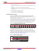
On the next rising CCLK edge, the device begins sampling the data pins. Pins D[0:15] are
sampled by Configuration until the bus width is determined. See Sync Word/Bus Width
Auto Detection, page 76 for details. After bus width is determined, the proper width of the
data bus is sampled for the synchronization word search. Configuration begins after the
synchronization word is clocked into the device.
After the configuration bitstream is loaded, the device enters the startup sequence. The
device asserts its DONE signal High in the phase of the startup sequence that is specified
by the bitstream (see Startup (Step 8) in Chapter 5). The configuration controller should
continue sending CCLK pulses until after the startup sequence has finished. (This can
require several CCLK pulses after DONE goes High. See Startup (Step 8) in Chapter 5 for
details).
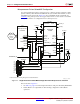
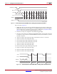
After configuration, the CSI_B and RDWR_B signals can be deasserted, or they can remain
asserted. Because the SelectMAP port is inactive, toggling RDWR_B at this time does not
cause an abort. Figure 2-8 summarizes the timing of SelectMAP configuration with
continuous data loading.