
User guide

30 www.xilinx.com Spartan-6 FPGA Configuration User Guide
UG380 (v2.7) October 29, 2014
Chapter 2: Configuration Interface Basics
SelectMAP Configuration Interface
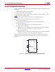
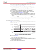
The SelectMAP configuration interface (Figure 2-5) provides an 8-bit or 16-bit bidirectional
data bus interface to the Spartan-6 device configuration logic that can be used for both
configuration and readback. (For details, refer to Chapter 6, Readback and Configuration
Veri fi cati on.) The bus width of SelectMAP is automatically detected (see Sync Word/Bus
Width Auto Detection, page 76). A simulation model for SelectMAP configuration is
available. For more information, consult UG626
, Synthesis and Simulation Guide.
CCLK is an output in Master SelectMAP mode, sourced by the internal oscillator or by the
GCLK0/USERCCLK pin. In Slave SelectMAP mode, CCLK is an input. One or more
Spartan-6 devices can be configured through the SelectMAP bus, in series or parallel.
There are multiple methods of configuring an FPGA in SelectMAP mode:
• Single-device Master SelectMAP
• Single-device Slave SelectMAP
• Typical setup includes a processor, providing data and clock.
•Multiple-device daisy-chain SelectMAP bus
• Multiple FPGAs are configured in series with different images from a PROM or
processor (see Chapter 9, Advanced Configuration Interfaces).
•Multiple-device ganged SelectMAP
• Multiple FPGAs are configured in parallel with the same image from a PROM or
processor (see Chapter 9, Advanced Configuration Interfaces).
Some SelectMAP considerations are:
• RDWR_B is a dual-function pin that can be a V
REF
pin in bank 2, but it cannot be
utilized as V
REF
when the SelectMAP configuration mode is used.
Master SelectMAP and Slave SelectMAP are described in this chapter; daisy-chain and
ganged configuration methods are described in Chapter 9, Advanced Configuration
Interfaces.
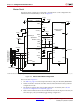
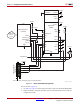
X-Ref Target - Figure 2-5
Figure 2-5: Spartan-6 FPGA SelectMAP Configuration Interface
DONE
CCLK
PROGRAM_B
INIT_B
D[15:0]
M[1:0]
CSI_B
RDWR_B
CSO_B
UG380_c2_05_042909