
User guide

Spartan-6 FPGA Configuration User Guide www.xilinx.com 29
UG380 (v2.7) October 29, 2014
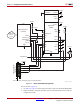
Serial Configuration Interface
3. The CCLK net requires Thevenin parallel termination. For more details, see Board
Layout for Configuration Clock (CCLK), page 54.
4. The DONE pin is by default an open-drain output with an internal pull-up. An
additional external pull-up is recommended. The DONE pin has a programmable
active driver that can be enabled via the BitGen option -g DriveDone.
5. The INIT_B pin is a bidirectional, open-drain pin. An external pull-up resistor is
recommended.
6. The SPI control pins, CSO_B and MOSI, toggle during serial configuration.
7. V
FS
is present in 6SLX75/T, 6SLX100/T, and 6SLX150/T devices, and is used for
eFUSE programming. See eFUSE, page 91 for more details.
8. V
BATT
is present in 6SLX75/T, 6SLX100/T, and 6SLX150/T devices, and is the power
source for AES key storage. If AES encryption is unused, V
BATT
can be tied to either
V
CCAUX
or ground, or left unconnected.
9. If VCCO_2 is 1.8V, V
CCAUX
must be 2.5V. If VCCO_2 is 2.5V or 3.3V, V
CCAUX
can be
either 2.5V or 3.3V.
10. The SUSPEND pin should be Low during power up and configuration. If the Suspend
feature is not used, the SUSPEND pin must be connected to ground.
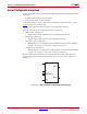
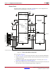
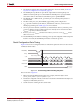
Serial Configuration Data Timing
Figure 2-4 shows how configuration data is clocked into Spartan-6 devices in Slave Serial
and Master Serial modes.
Notes relevant to Figure 2-4:
1. Bit 0 represents the MSB of the first byte. For example, if the first byte is 0xAA
(1010_1010), bit 0 = 1, bit 1 = 0, bit 2 = 1, etc.
2. For Master configuration mode, CCLK does not transition until after the Mode pins are
sampled, as indicated by the arrow.
3. CCLK can be free-running in Slave Serial mode.
X-Ref Target - Figure 2-4
Figure 2-4: Serial Configuration Clocking Sequence
PROGRAM_B
INIT_B
CCLK
DONE
Master DIN
Master CLK begins here
Data bits clocked out on falling edge of CCLK
UG380_c2_04_0121012
BIT 0 BIT 1 BIT n BIT n+1
Master DOUT