
User guide

28 www.xilinx.com Spartan-6 FPGA Configuration User Guide
UG380 (v2.7) October 29, 2014
Chapter 2: Configuration Interface Basics
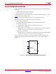
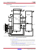
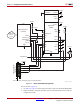
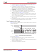
Notes relevant to Figure 2-3:
1. See Table 5-2, page 72 for internal pin terminations and pins affected by HSWAPEN.
2. DOUT should be connected to the DIN of the downstream FPGA for daisy-chained
configuration modes.
X-Ref Target - Figure 2-3
Figure 2-3: Slave Serial Mode Configuration
TDI
TDO
TMS
TCK
PROGRAM_B
VCCINT
VCCAUX
VCCO_2
VCCO_1
INIT_B
DONE
GND
HSWAPEN
VCCO_0
VCCO_0
4.7 k
M1
M0
DOUT
330
DIN
CCLK
4.7 kΩ
CLOCK
SERIAL_OUT
PROGRAM_B
PROGRAM_B
INIT_B
DONE
VCC
GND
Configuration
Memory
Source
UG380_c2_03_071910
Spartan-6
FPGA
VCCO_2
VCCO_2
VCCO_1
VCCO_2
VCCAUX
VFS
VBATT
VCCO_2
VCCO_2
Microprocessor
or CPLD
1
14
Xilinx Cable Header
(JTAG Interface)
VREF
TMS
TCK
TDO
TDI
N.C.
N.C.
VCCAUX
Refer to the Notes following this figure for related information.
MOSI
CSO_B
VFS
VBATT
SUSPEND