
User guide

26 www.xilinx.com Spartan-6 FPGA Configuration User Guide
UG380 (v2.7) October 29, 2014
Chapter 2: Configuration Interface Basics
Master Serial
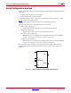
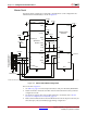
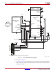
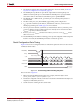
The Master Serial configuration is designed so that the FPGA can be configured from a
Xilinx® Platform Flash PROM, as shown in Figure 2-2.
Notes relevant to Figure 2-2:
1. See Table 5-2, page 72 for internal pin terminations and pins affected by HSWAPEN.
2. DOUT should be connected to the DIN of the downstream FPGA for daisy-chained
configuration modes.
3. The CCLK net requires Thevenin parallel termination. For details, refer to Board
Layout for Configuration Clock (CCLK), page 54.
4. Master Serial and Master SPI are both enabled from the same mode pins. Therefore, the
SPI control pins, CSO_B and MOSI, toggle during configuration.
X-Ref Target - Figure 2-2
Figure 2-2: Master Serial Mode Configuration
Platform Flash
XCFxxS
UG380_c2_02_011513
VCCINT
DIN D0
VCCINT
GND
MOSI
CSO_B
DOUT
CCLK
HSWAPEN
VCCO_0
VCCO_1
INIT_B
CLK
TMS
TCK
TDI
CE
OE/RESET
VCCO
VCCO_2
M1
M0
TMS
TDO
TCK
TDI
PROGRAM_B
DONE
GND
VCCJ
CEO
TDO
PROGRAM_B
VREF
TMS
TCK
TDO
TDI
N.C.
N.C.
1
14
(JTAG Interface)
Xilinx Cable Header
Spartan-6
FPGA
VCCO_2
VCCO_2
4.7 kΩ
VCCO_2
VCCO_2
VCCAUX
VCCO_2
VCCAUX
VCCO_2
4.7 kΩ
VCCO_0
VCCO_1
VCCO_2
330Ω
Refer to the Notes following this figure for related information.
VCCAUX
VCCAUX
VFS
VBATT
VFS
VBATT
SUSPEND