
User guide

24 www.xilinx.com Spartan-6 FPGA Configuration User Guide
UG380 (v2.7) October 29, 2014
Chapter 2: Configuration Interface Basics
Serial Configuration Interface
In serial configuration modes, the FPGA is configured by loading one configuration bit per
CCLK cycle:
• In Master Serial mode, CCLK is an output.
• In Slave Serial mode, CCLK is an input.
A simulation model for serial configuration is available. For more information, consult
UG626
, Synthesis and Simulation Guide.
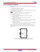
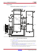
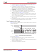
Figure 2-1 shows the basic Spartan-6 FPGA serial configuration interface.
There are four methods of configuring an FPGA in serial mode:
• Master Serial configuration:
• Typical setup includes a PROM such as the Platform Flash XCFxxS.
• Slave Serial configuration
• Typical setup includes a processor providing data and clock.
• Serial daisy-chain configuration
• Multiple FPGAs are configured in series with different images from a PROM or
processor (see Chapter 9, Advanced Configuration Interfaces).
• Ganged Serial configuration
• Multiple FPGAs are configured in parallel with the same image from a PROM or
processor (see Chapter 9, Advanced Configuration Interfaces).
Master and Slave Serial configuration are described in this chapter, daisy-chain and
ganged configuration methods are discussed in Chapter 9, Advanced Configuration
Interfaces.
X-Ref Target - Figure 2-1
Figure 2-1: Spartan-6 FPGA Serial Configuration Interface
DOUT
DONE
CCLK
PROGRAM_B
INIT_B
DIN
M[1:0]
UG380_c2_01_042909