
User guide

Spartan-6 FPGA Configuration User Guide www.xilinx.com 23
UG380 (v2.7) October 29, 2014
Chapter 2
Configuration Interface Basics
This chapter provides quick access to the most commonly used configuration solutions for
Spartan®-6 FPGA devices. It includes several different methods and gives the appropriate
connections, terminations, signal definitions, and basic timing descriptions. Additional
detail is included in Chapter 9, Advanced Configuration Interfaces, which covers more
advanced arrangements as well as more detail on error recovery and further explanation of
some of the ideas initially summarized here.
Spartan-6 devices support all the configuration modes supported by the Extended
Spartan-3A family. However, the difference is Spartan-6 devices only expose two mode
pins M[1:0], which define the configuration modes, instead of three mode pins M[2:0] used
by the Extended Spartan-3A family. The mode pins are described in Table 2-1. Detailed
interface timing information is located in DS162
, Spartan-6 FPGA Data Sheet: DC and
Switching Characteristics.
JTAG Interface
While there is no specific mode for JTAG, the JTAG interface is available as a configuration
interface any time the device is powered. For more information, refer to Chapter 3,
Boundary-Scan and JTAG Configuration.
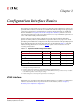
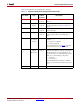
Table 2-1: Spartan-6 FPGA Configuration Modes
Configuration Mode M[1:0] Bus Width CCLK Direction
Master Serial/SPI 01 1, 2, 4
(1)
Output
Master SelectMAP/BPI
(2)
00 8, 16 Output
JTAG
(3)
xx 1 Input (TCK)
Slave SelectMAP
(2)
10 8, 16 Input
Slave Serial
(4)
11 1 Input
Notes:
1. Utilizing dual and quad SPI modes.
2. Parallel configuration mode bus is auto-detected by the configuration logic.
3. Spartan-6 devices also have a dedicated four-wire JTAG (IEEE Std 1149.1) port that is always available
to the FPGA regardless of the mode pin settings.
4. Default setting due to internal pull-up termination on Mode pins.