
User guide


168 www.xilinx.com Spartan-6 FPGA Configuration User Guide
UG380 (v2.7) October 29, 2014
Chapter 10: Advanced JTAG Configurations
Multiple Device Configuration
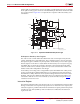
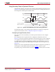
It is possible to configure multiple Spartan-6 devices in a chain. (See Figure 10-6.) The
devices in the JTAG chain are configured one at a time. The multiple device configuration
steps can be applied to any size chain.
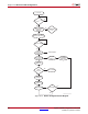
Refer to the state diagram in Figure 10-1 for the following TAP controller steps:
1. On power-up, place a logic 1 on the TMS and clock the TCK five times. This ensures
starting in the TLR (Test-Logic-Reset) state.
2. Load the CFG_IN instruction into the target device (and BYPASS in all other devices).
Go through the RTI state (RUN-TEST/IDLE).
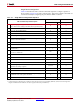
3. Load in the configuration bitstream per step 7 through step 11 in Table 10-4.
4. Repeat step 2 and step 3 for each device.
5. Load the JSTART command into all devices.
6. Go to the RTI state and clock TCK 16 times.
All devices are active at this point.
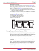
Clocking Startup and Shutdown Sequences (JTAG)
There are three clock sources for startup and shutdown sequence: CCLK, UserCLK, and
JTAGCLK. Clock selection is set by BitGen. The startup sequence is executed in the
ISC_Accessed state. When it is clocked by JTAGCLK, the startup sequence receives the
JTAGCLK in TAP Run/Test Idle state while ISC_DISABLE is the current JTAG instruction.
The number of clock cycles in Run/Test Idle state for successful completion of
ISC_DISABLE is determined by the number of clock cycles needed to complete the startup
sequence.
When UserCLK or CCLK is used to clock the startup sequence, the user should know how
many JTAGCLK cycles should be spent in Run/Test Idle to complete the startup sequence
successfully.
The shutdown sequence is executed when the device transitions from the Operational to
the ISC_Accessed state. Shutdown is done while executing the ISC_ENABLE instruction.
When the shutdown sequence is clocked using JTAGCLK, the clock is supplied in the
Run/Test Idle state of the ISC_ENABLE instruction. The number of clock cycles in
Run/Test Idle is determined by the number of clock cycles needed to complete the
shutdown sequence.
X-Ref Target - Figure 10-6
Figure 10-6: Boundary-Scan Chain of Devices
JTAG Header
UG380_c10_06_042909
TDOTDI
TMS
TCK
PROGRAM_B
TDI
TMS
TCK
PROGRAM_B
TDO
Spartan-6
FPGA
Spartan-6
FPGA
Spartan-6
FPGA
TDI
TMS
TCK
PROGRAM_B
TDO
Device 0 Device 1 Device 2
TDO
TMS
TDI
TCK