
User guide


Spartan-6 FPGA Configuration User Guide www.xilinx.com 165
UG380 (v2.7) October 29, 2014
JTAG Configuration/Readback
Using Boundary-Scan in Spartan-6 Devices
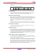
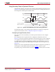
Characterization data for some of the most commonly requested timing parameters shown
in Figure 10-4 is listed in the Spartan-6 FPGA Data Sheet: DC and Switching Characteristics in
the Configuration Switching Characteristics table.
For further information on the startup sequence, bitstream, and internal configuration
registers referenced here, refer to Configuration Sequence in Chapter 5.
Configuring through Boundary-Scan
One of the most common boundary-scan vendor-specific instructions is the configure
instruction.
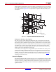
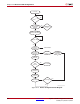
The configuration flow for Spartan-6 device configuration with JTAG is shown in
Figure 10-5. The sections that follow describe how the Spartan-6 device can be configured
as a single device through the boundary-scan or as part of a multiple-device scan chain.
A configured device can be reconfigured by toggling the TAP and entering a CFG_IN
instruction after pulsing the PROGRAM_B pin or issuing the shut-down sequence. (See
Figure 10-5.)
Designers who wish to implement the Spartan-6 FPGA JTAG configuration algorithm are
encouraged to use the SVF-based flow provided in XAPP058
, Xilinx In-System
Programming Using an Embedded Microcontroller and XAPP424
, Embedded JTAG ACE Player.
X-Ref Target - Figure 10-4
Figure 10-4: Spartan-6 FPGA Boundary-Scan Port Timing Waveforms
UG380_c10_04_042909
Data to be captured
Data to be driven out
TDO
TCK
TDI
TMS
Data Valid
Data Valid
T
TCKTDO
T
TAPTCK
T
TCKTAP