
User guide


160 www.xilinx.com Spartan-6 FPGA Configuration User Guide
UG380 (v2.7) October 29, 2014
Chapter 10: Advanced JTAG Configurations
Spartan-6 devices support the mandatory IEEE Std 1149.1 commands as well as several
Xilinx vendor-specific commands. The EXTEST, INTEST, SAMPLE, BYPASS, IDCODE,
USERCODE, and HIGHZ instructions are all included. The TAP also supports internal
user-defined registers (USER1, USER2, USER3, and USER4) and configuration/readback
of the device.
The Spartan-6 FPGA boundary-scan operations are independent of mode selection. The
boundary-scan mode in Spartan-6 devices overrides other mode selections. For this
reason, boundary-scan instructions using the boundary-scan register
(SAMPLE/PRELOAD, INTEST, and EXTEST) must not be performed during
configuration. All instructions except the user-defined instructions are available before a
Spartan-6 device is configured. After configuration, all instructions are available.
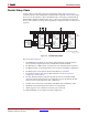
When boundary-scan testing is carried out on a configured Spartan-6 device, and the IOB
is configured to include an inverter, incorrect values can be driven by EXTEST and read on
the SAMPLE instructions. When the IOB is configured to include an inverter, this inverter
is included on the path from the pad to the boundary-scan cell. This results in unexpected
values being driven and/or sampled by the cell. The SAMPLE, PRELOAD, EXTEST, and
INTEST JTAG instructions can all be affected.
There are a number of alternatives that can be employed.
1. Prevent FPGA configuration. This can be achieved by holding the INIT_B pin Low, or
alternatively changing the Mode pin values if configuring from flash.
2. Clear prior configuration using PROGRAM_B pin or a power cycle and prevent
reconfiguration.
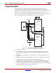
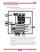
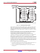
X-Ref Target - Figure 10-2
Figure 10-2: Boundary-Scan TAP Controller
1
UG380_c11_02_051109
TEST-LOGIC-RESET
0
RUN-TEST/IDLE
1
SELECT-DR-SCAN
0
1
0
CAPTURE-DR CAPTURE-IR
0
1
0
0
SHIFT-DR SHIFT-IR
1
0
1
0
EXIT1-DR EXIT1-IR
0
1
0
PAUSE-DR PAUSE-IR
1
0
1
EXIT2-DR
1
EXIT2-IR
1
UPDATE-DR
1
UPDATE-IR
1
SELECT-IR-SCAN
0
1 0
0
0
1
1
0
Note: The value shown adjacent to each state transition represents the signal
present at TMS at the time of a rising edge at TCK.