
User guide


158 www.xilinx.com Spartan-6 FPGA Configuration User Guide
UG380 (v2.7) October 29, 2014
Chapter 10: Advanced JTAG Configurations
JTAG Configuration/Readback
TAP Controller and Architecture
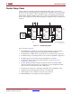
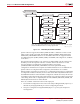
The Spartan-6 FPGA TAP contains four mandatory dedicated pins as specified by the
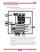
protocol given in Table 3-1 and illustrated in Figure 10-1, a typical JTAG architecture.
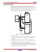
Figure 10-1 diagrams a 16-state finite state machine. The four TAP pins control how data is
scanned into the various registers. The state of the TMS pin at the rising edge of TCK
determines the sequence of state transitions. There are two main sequences, one for
shifting data into the data register and the other for shifting an instruction into the
instruction register.
A transition between the states only occurs on the rising edge of TCK, and each state has a
different name. The two vertical columns with seven states each represent the Instruction
Path and the Datapath. The data registers operate in the states whose names end with
"DR," and the instruction register operates in the states whose names end in "IR." The states
are otherwise identical.
X-Ref Target - Figure 10-1
Figure 10-1: Typical JTAG Architecture
IEEE Standard 1149.1 Compliant Device
TMS
Instruction Register
Instruction Decoder
Bypass[1] Register
IDCODE[32] Register
Boundary-Scan[N] Register
Select Data
Register
Shift-IR/Shift-DR
Select Next State
TAP State Machine
TCK
TDI
TDO
I/O I/O I/O I/O
Te st-Logic-Reset
Run-Test/Idle
Select-DR
Capture-DR
Shift-DR
Exit1-DR
Pause-DR
Exit2-DR
Update-DR
0
0
0
0
0
0
0
0
1
1
1
1
1
1
1
Select-IR
Capture-IR
Shift-IR
Exit1-IR
Pause-IR
Exit2-IR
Update-IR
0
0
0
0
0
0
1
1
1
1
1
1
0
0
11
UG380_c10_01_042909