
User guide

154 www.xilinx.com Spartan-6 FPGA Configuration User Guide
UG380 (v2.7) October 29, 2014
Chapter 9: Advanced Configuration Interfaces
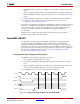
Readback Abort Sequence Description
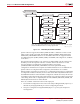
An ABORT is signaled during readback as follows:
1. The readback sequence begins normally.
2. The user pulls the RDWR_B pin Low while the device is selected (CSI_B asserted
Low).
3. BUSY goes High if CSI_B remains asserted (Low).
4. The ABORT ends when CSI_B is deasserted.
ABORTs during readback are not followed by a status word because the RDWR_B signal is
set for write control (FPGA D[x:0] pins are inputs).
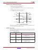
ABORT Status Word
During the configuration ABORT sequence, the device drives a status word onto the D[7:0]
pins. The status bits do not bit swap. The other data pins are always High. The key for that
status word is given in Table 9-2.
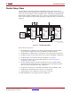
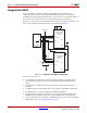
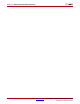
X-Ref Target - Figure 9-7
Figure 9-7: Readback Abort Sequence
D[0:7]
BUSY
CCLK
FPGA
ABORT
UG380_c9_07_052009
CSI_B
RDWR_B
Table 9-2: ABORT Status Word
Bit Number Status Bit Name Meaning
D7 CFGERR_B
Configuration error (active Low)
0 = A configuration error has occurred.
1 = No configuration error.
D6 DALIGN
Sync word received (active High)
0 = No sync word received.
1 = Sync word received by interface logic.
D5 RIP
Readback in progress (active High)
0 = No readback in progress.
1 = A readback is in progress.