
User guide

Spartan-6 FPGA Configuration User Guide www.xilinx.com 151
UG380 (v2.7) October 29, 2014
Parallel Daisy-Chain
Parallel Daisy-Chain
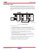
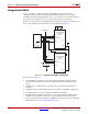
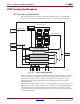
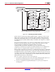
Spartan-6 FPGA configuration supports parallel daisy-chains. Figure 9-4 shows an
example schematic of the leading device in Master BPI configuration mode. The leading
device can also be in Master or Slave SelectMAP modes. The D[15:0], CCLK, RDWR_B,
PROGRAM_B, DONE, and INIT_B pins share a common connection between all of the
devices. The CSI_B pins are daisy-chained, gating the configuration data to each device in
sequence.
Notes relevant to Figure 9-4:
1. The DONE pin is by default an open-drain output requiring an external pull-up
resistor. In this arrangement, the active DONE driver must be disabled.
2. The INIT_B pin is a bidirectional, open-drain pin. An external pull-up is required.
3. The BitGen startup clock setting must be set for CCLK for SelectMAP configuration.
4. The BUSY signals can be left unconnected if readback is not needed.
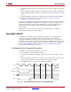
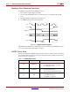
5. The CCLK net requires Thevenin parallel termination. See Board Layout for
Configuration Clock (CCLK).
6. The FCS_B, FWE_B, FOE_B, CSO_B weak pull-up resistors should be enabled,
otherwise external pull-up resistors are required for each pin. By default, all dual-
mode I/Os have weak pull-downs after configuration.
7. The first device in the chain can be Master SelectMAP, Slave SelectMAP, or BPI.
8. Readback in the parallel daisy-chain scheme is not supported.
9. AES decryption is not available in x16 mode, only in x8 mode.
10. Fallback MultiBoot is not supported in this configuration.
X-Ref Target - Figure 9-4
Figure 9-4: Parallel Daisy-Chain
UG380_c9_04_071910
Flash
A[25:0]
D[15:0]
FCS_B
FOE_B
FWE_B
Spartan-6
FPGA
A[25:0]
D[15:0]
FCS_B
FOE_B
FWE_B
BUSY
INIT_B
DONE
CSO_B
CCLK
M1 M0
Spartan-6
FPGA
D[15:0]
CSI_B
RDWR_B
CCLK
BUSY
INIT_B
DONE
CSO_B
M1 M0
Spartan-6
FPGA
D[15:0]
CSI_B
RDWR_B
CCLK
BUSY
INIT_B
DONE
CSO_B
No
Connect
M[1:0]=Slave SelectMAP
M1 M0
M[1:0]=Slave SelectMAP
BPI
0 0
1 0 1 0
330Ω
330Ω
330Ω
4.7 kΩ