
User guide

Spartan-6 FPGA Configuration User Guide www.xilinx.com 149
UG380 (v2.7) October 29, 2014
Multiple Device SelectMAP Configuration
9. Ganged serial configuration is specific to the Platform Flash (XCFxxS and XCFxxP)
PROMs and SPI serial flash only.
10. Fallback MultiBoot is not supported in this configuration.
There are a number of important considerations for ganged serial configuration:
•Startup sequencing (GTS)
GTS should be released before DONE or during the same cycle as DONE to ensure all
devices are operational when all DONE pins have been released.
• Disable the active DONE driver for all devices
For ganged serial configuration, the active DONE driver must be disabled for all
devices if the DONE pins are tied together, because there can be variations in the
startup sequencing of each device. A pull-up resistor is therefore required on the
common DONE signal.
-g DriveDone:no (BitGen option, all devices)
• Connect all DONE pins if using a Master device
It is important to connect the DONE pins for all devices in ganged serial configuration
if one FPGA is used as the Master device. Failing to connect the DONE pins can cause
configuration to fail for individual devices in this case. If all devices are set for Slave
Serial mode, the DONE pins can be disconnected (if the external CCLK source
continues toggling until all DONE pins go High).
For debugging purposes, it is often helpful to have a way of disconnecting individual
DONE pins from the common DONE signal.
•DONE pin rise time
After all DONE pins are released, the DONE pin should rise from logic 0 to logic 1 in
one CCLK cycle. If additional time is required for the DONE signal to rise, the BitGen
-g DonePipe option can be set for all devices in the serial daisy-chain.
• Configuration Clock (CCLK) as the clock signal for board layout
The CCLK signal is relatively slow, but the edge rates on the Spartan-6 FPGA input
buffers are very fast. Even minor signal integrity problems on the CCLK signal can
cause the configuration to fail. (Typical failure mode: DONE Low and INIT_B High.)
Therefore, design practices that focus on signal integrity, including signal integrity
simulation with IBIS, are recommended.
•Signal fanout
Designers must focus on good signal integrity when using ganged serial
configuration. Signal integrity simulation is recommended.
• PROM files for ganged serial configuration
PROM files for ganged serial configuration are identical to the PROM files used to
configure single devices. There are no special PROM file considerations.
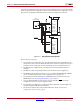
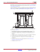
Multiple Device SelectMAP Configuration
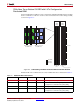
Multiple Spartan-6 devices in Slave SelectMAP mode can be connected on a common
SelectMAP bus (Figure 9-3). In a SelectMAP bus, the D, CCLK, RDWR_B, BUSY,
PROGRAM_B, DONE, and INIT_B pins share a common connection between all of the
devices. To allow each device to be accessed individually, the CSI_B (Chip Select) inputs
must not be tied together. External control of the CSI_B signal is required and is usually
provided by a microprocessor or CPLD.