
User guide

148 www.xilinx.com Spartan-6 FPGA Configuration User Guide
UG380 (v2.7) October 29, 2014
Chapter 9: Advanced Configuration Interfaces
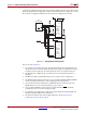
typically set for Master Serial mode (to drive CCLK) while the others are set for Slave Serial
mode. For ganged serial configuration, all devices must be identical. Configuration can be
driven from a configuration PROM or from an external configuration controller.
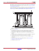
Notes relevant to Figure 9-2:
1. For ganged serial configuration, the optional DONE driver must be disabled for all
devices if one device is set for Master mode because each device might not start up on
exactly the same CCLK cycle. An external pull-up resistor is required in this case.
2. The INIT_B pin is a bidirectional, open-drain pin. An external pull-up resistor is
required.
3. The BitGen startup clock setting must be set for CCLK for serial configuration.
4. The PROM in this diagram represents one or more Xilinx PROMs. Multiple PROMs
can be cascaded to increase the overall configuration storage capacity.
5. The
BIT file must be reformatted into a PROM file before it can be stored on the
PROM. Refer to the Generating PROM Files, page 77 section.
6. On some Xilinx PROMs, the reset polarity is programmable. RESET
should be
configured as active Low when using this setup.
7. For ganged serial configuration, all devices must be identical (same IDCODE) and
must be configured with the same bitstream.
8. The CCLK net requires Thevenin parallel termination. See Board Layout for
Configuration Clock (CCLK), page 54.
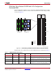
X-Ref Target - Figure 9-2
Figure 9-2: Ganged Serial Configuration
D0
PROGRAM
CLK
DOUTDIN
M1M0
M1M0
CCLK
PROGRAM_B
DONE
DIN
CCLK
PROGRAM_B
DONE
INIT_B
DOUT
INIT_B
CE
RESET/OE
UG380_c9_02_052009
Xilinx
Platform PROM
Spartan-6
FPGA
Master
Serial
Spartan-6
FPGA
Slave
Serial