
User guide

Spartan-6 FPGA Configuration User Guide www.xilinx.com 147
UG380 (v2.7) October 29, 2014
Ganged Serial Configuration
Guidelines and Design Considerations for Serial Daisy-Chains
There are a number of important considerations for serial daisy-chains:
Startup Sequencing (GTS)
GTS should be released before DONE or during the same cycle as DONE to ensure the
Spartan-6 device is operational when all DONE pins have been released.
Active DONE Driver
All devices except the first should disable the driver on the DONE pin (refer to the BitGen
section of UG628
, Command Line Tools User Guide for software settings). The first device in
a chain is programmed last:
• DriveDone is disabled (all devices except the first)
• DriveDone is enabled (first device)
Alternatively, the driver can be disabled for all DONE pins and an external pull-up resistor
can be added to pull the signal High after all devices have released it.
Connect All DONE Pins
It is important to connect the DONE pins for all devices in a serial daisy-chain. Failing to
connect the DONE pins can cause configuration to fail. For debugging purposes, it is often
helpful to have a way of disconnecting individual DONE pins from the common DONE
signal, so that devices can be individually configured through the serial or JTAG interface.
DONE Pin Rise Time
After all DONE pins are released, the DONE pin should rise from logic 0 to logic 1 in one
CCLK cycle. External pull-up resistors are required. If additional time is required for the
DONE signal to rise, the BitGen DonePipe option can be set for all devices in the serial
daisy-chain. (Refer to the BitGen section of UG628
, Command Line Tools User Guide for
software settings.)
Bitstream Formatting
Bitstreams must be customized to inform the FPGAs that more than one bitstream is being
delivered and to cascade information to downstream devices. This must be done by using
PROMGen, a PROM file formatting tool located within the iMPACT programming tool.
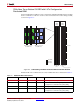
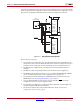
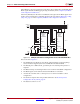
Ganged Serial Configuration
More than one device can be configured simultaneously from the same bitstream using a
ganged serial configuration setup (Figure 9-2). In this arrangement, the serial configuration
pins are tied together such that each device sees the same signal transitions. One device is
Table 9-1: Maximum Number of Configuration Bits, Various Device Families
Architecture Maximum DOUT Bits
Spartan-6, Spartan-3, Virtex-6, Virtex-5, Virtex-4,
Virtex-II Pro, and Virtex-II Devices
32 x (2
27
– 1) = 4,294,967,264
Virtex, Virtex-E, Spartan-II, and Spartan-IIE Devices 32 x (2
20
– 1) = 33,554,216