
User guide

146 www.xilinx.com Spartan-6 FPGA Configuration User Guide
UG380 (v2.7) October 29, 2014
Chapter 9: Advanced Configuration Interfaces
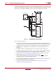
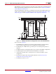
3. The BitGen startup clock setting must be set for CCLK for serial configuration.
4. The PROM in this diagram represents one or more Xilinx® PROMs. Multiple Xilinx
PROMs can be cascaded to increase the overall configuration storage capacity.
5. The BIT file must be reformatted into a PROM file before it can be stored on the Xilinx
PROM.
6. The CCLK net requires Thevenin parallel termination. See Board Layout for
Configuration Clock (CCLK), page 54.
7. Serial daisy-chains are specific to the Platform Flash (XCFxxS and XCFxxP) PROMs
and SPI serial flash only.
The first device in a serial daisy-chain is the last to be configured. CRC checks only include
the data for the current device, not for any others in the chain.
After the last device in the chain finishes configuration and passes its CRC check, it enters
the Startup sequence. At the Release DONE pin phase in the Startup sequence, the device
places its DONE pin in a High-Z state while the next to the last device in the chain is
configured. After all devices release their DONE pins, the common DONE signal is either
pulled High externally or driven High by the first device in the chain. On the next rising
CCLK edge, all devices move out of the Release DONE pin phase and complete their startup
sequences.
It is important that all DONE pins in a Slave Serial daisy-chain be connected. Only the first
device in the serial daisy-chain should have the DONE active pull-up driver enabled.
Enabling the DONE driver on downstream devices causes contention on the DONE signal.
If using SPI in a serial daisy-chain configuration, the slave FPGAs must be configured with
a design prior to attempting to indirectly program the SPI flash through the master FPGA.
Not doing so causes indirect programming to fail.
Mixed Serial Daisy-Chains
Spartan-6 devices can be daisy-chained with the Spartan-3, Virtex®-4, and Virtex-5
families. There are three important design considerations when designing a mixed serial
daisy-chain:
• Many older FPGA devices cannot accept as fast a CCLK frequency as a
Spartan-6 device can generate. Select a configuration CCLK speed supported by all
devices in the chain.
• Spartan-6 devices should always be at the beginning of the serial daisy-chain, with
older family devices located at the end of the chain.
• These device families have similar BitGen options. The guidelines provided for
Spartan-6 FPGA BitGen options should be applied to all devices in a serial daisy-
chain.
• The number of configuration bits that a device can pass through its DOUT pin is
limited. This limit varies for different families (Table 9-1). The sum of the bitstream
lengths for all downstream devices must not exceed the number in Table 9-1 for each
family.