
User guide

Spartan-6 FPGA Configuration User Guide www.xilinx.com 145
UG380 (v2.7) October 29, 2014
Chapter 9
Advanced Configuration Interfaces
Serial Daisy-Chains
Multiple Spartan®-6 devices can be configured from a single configuration source by
arranging the devices in a serial daisy-chain. In a serial daisy-chain, devices receive their
configuration data through their DIN pin, passing configuration data along to
downstream devices through their DOUT pin. The device closest to the configuration data
source is considered the most upstream device, while the device furthest from the
configuration data source is considered the most downstream device.
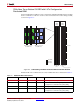
In a serial daisy-chain, the configuration clock is typically provided by the most upstream
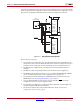
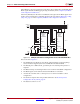
device in Master Serial mode. All other devices are set for Slave Serial mode. Figure 9-1
illustrates this configuration.
Another alternative is to use SPI mode for the first device. The daisy-chain data is still sent
out through DOUT in SPI mode.
Notes relevant to Figure 9-1:
1. The DONE pin is by default an open-drain output requiring an external pull-up
resistor. For all devices except the first, the active driver on DONE must be disabled.
For the first device in the chain, the active driver on DONE can be enabled. See
Guidelines and Design Considerations for Serial Daisy-Chains.
2. The INIT_B pin is a bidirectional, open-drain pin. An external pull-up resistor is
required.
X-Ref Target - Figure 9-1
Figure 9-1: Master/Slave Serial Mode Daisy-Chain Configuration
Spartan-6 FPGA
Master
Serial
D0 DOUT
INIT_B
DIN
CCLK
PROGRAM_B
DONE
M0 M1
CLK
CE
RESET/OE
PROGRAM
Spartan-6 FPGA
Slave
Serial
DOUT
INIT_B
DIN
CCLK
PROGRAM_B
DONE
M0 M1
UG380_c9_01_011513
4.7 kΩ
330Ω
Xilinx
Platform Flash PROM