
User guide

136 www.xilinx.com Spartan-6 FPGA Configuration User Guide
UG380 (v2.7) October 29, 2014
Chapter 7: Reconfiguration and MultiBoot
register or setting the BitGen option TIMER_CFG. The default is 64k clock cycles, and the
minimum value is 16h'0201.
The watchdog timer cannot be disabled by the user. The watchdog timer is disabled during
and after fallback reconfiguration.
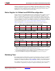
Required Data Spacing between MultiBoot Images
Spartan-6 FPGA MultiBoot addressing is flexible enough to allow a bitstream to begin at
any byte boundary. However, there are a few practical limitations, based on specific
application requirements.
Flash Sector, Block, or Page Boundaries
Spartan-6 FPGAs load MultiBoot configuration images from an external flash PROM. All
flash PROMs have an internal memory architecture that arranges the memory into sectors,
blocks, or pages. Nearly all PROMs have multiple sectors. Some architectures provide
additional granularity, splitting a sector into smaller blocks, or even smaller still, pages.
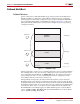
Ideally, a Spartan-6 FPGA MultiBoot configuration image should be aligned to a sector,
block, or page boundary. The specific requirement depends on the flash PROM
architecture. If the smallest erasable element in the flash PROM is a sector, then the FPGA
bitstream must be aligned to a sector boundary. This way, one FPGA bitstream can be
updated without affecting others in the PROM.
Additional Memory Space Required for LCK_Cycle
A Spartan-6 FPGA application can contain one or more digital clock managers (DCMs) or
phase-locked loops (PLLs). The LCK_Cycle BitGen setting determines if, during
configuration, the FPGA waits for all of the clock elements to acquire and lock to their
respective input clock frequency before allowing the FPGA to finish the configuration
process. The lock time, which is specified in D
S162, Spartan-6 FPGA Data Sheet: DC and
Switching Characteristics, depends on the DCM or PLL mode, and the input clock frequency.
Even if the FPGA is waiting for one or more clock elements to lock before completing
configuration, the FPGA’s configuration controller continues searching for the next
synchronization word. If two adjacent MultiBoot images are placed with one immediately
following the other and the first FPGA bitstream contains a DCM or PLL with the
LCK_Cycle option set, then potential configuration problems can occur. If the controller
sees the synchronization word in the second FPGA bitstream before completing the
current configuration, it starts interpreting data from the second bitstream. However, the
FPGA’s configuration logic can complete the current configuration even though the FPGA
has read data from the second bitstream. If this condition applies to a design, sufficient
spacing must exist between bitstreams.
For more information on MultiBoot in Spartan-6 FPGAs, see the SP605 Evaluation Kit
design files
.