
User guide

Spartan-6 FPGA Configuration User Guide www.xilinx.com 133
UG380 (v2.7) October 29, 2014
Fallback MultiBoot
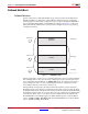
There are three images for MultiBoot configuration. The first image is the Header. This
small bitstream contains the sync word, sets the addresses for the next bitstream as well as
the fallback or golden bitstream, and ends with an IPROG command. To generate this
bitstream automatically, add the BitGen option -g next_config_addr when creating
the programming file for the golden bitstream.
The second image is the MultiBoot bitstream. This is the bitstream that the user plans to
configure first. The location of this bitstream is defined by the values of GENERAL1,2. The
upper eight bits of the GENERAL 2 register are reserved for the opcode for the non-volatile
device. See Chapter 5, Configuration Details, for more information.
The third image is the fallback or golden bitstream. This bitstream is known to be “safe”
should an error occur consistently during configuration. The location of this bitstream is
defined by the values of GENERAL3,4. As with GENERAL1,2, the upper eight bits of
GENERAL4 are reserved for the opcode of the non-volatile device.
If the configuration fallback occurs and the golden bitstream is reached, the only way to
boot back into the MultiBoot bitstream (located at GENERAL1,2) is to toggle the
PROGRAM_B pin, power cycle the device, or use IPROG reconfiguration (see IPROG
Reconfiguration, page 134)
For designs that use more than two bitstreams, the GENERAL1,2 values must be set to the
location of the next bitstream then an IPROG command needs to be issued. GENERAL3,4
values should be reserved for the fallback bitstream.
The header image must start at address 0. This image has three “strikes” allotted to it. If a
CRC error is detected, the strike count increments and configuration restarts if the register
setting RESET_ON_ERROR is 1 (located in the register COR2, and can be set from BitGen
setting -g Reset_on_err) and the strike count is less than 3. The same behavior occurs
if the watchdog timer times out, but it does not depend on RESET_ON_ERROR. The strike
counter is found in the BOOTSTS registers. If the count is 3, configuration halts with INIT
and DONE driven Low.
The MultiBoot image can reside at any address specified in GENERAL1,2. This image has
three “strikes” allotted to it. If an error is detected, the strike count increments and
configuration will restart at the address specified in GENERAL1,2 if the count is less than
3 and RESET_ON_ERROR is 1. If the count hits 3, configuration moves to the fallback
bitstream located at GENERAL3,4. There are two ways to clear the strike count: power
cycle the FPGA or pulse the PROGRAM_B pin.
The fallback (or golden) image can reside at any address specified in GENERAL3,4. This
image has 3 strikes allotted to it. If an error is detected, the strike count increments and
configuration will restart at the address specified in GENERAL3,4 if the count is less than
6. The value is 6 because it shares the strike counter with the MultiBoot image. If the count
reaches 6, configuration boots back to zero, where the header image is located. When this
occurs, configuration will attempt both the MultiBoot image and the fallback image three
more times before halting configuration. This results in a strike count of 9.
After successful fallback reconfiguration, the user design should readback the STATUS or
BOOTSTS registers to verify the fallback was successful. Successful fallback configuration
maintains the strike count register, and a subsequent soft reboot uses the address stored in
GENERAL3,4 (the golden image). There are two ways to clear the strike count: perform a
hard reboot (pulse the PROGRAM_B pin) or cycle power.
If fallback reconfiguration exhausts all three strikes out, configuration stops and both
INIT_B and DONE are held Low.
Fallback is disabled if AES is enabled and for Slave configuration mode.