Spartan-6 FPGA Configuration User Guide UG380 (v2.
Notice of Disclaimer The information disclosed to you hereunder (the “Materials”) is provided solely for the selection and use of Xilinx products.
Revision History The following table shows the revision history for this document. Date Version Revision 06/24/2009 1.0 Initial Xilinx release. 02/17/2010 2.0 Changed REBOOT command to IPROG command throughout the document. Chapter 1: In The High-Speed Priority Option, changed the configuration data size to 3.6 Mb (XC6SLX16). In FPGA Density Migration on page 21, changed the required configuration memory size to 2.6 Mb (XC6SLX9) and 3.6 Mb (XC6SLX16).
Date Version Revision 02/22/2010 2.1 Changed the supported encryption data widths to x1 and x8 in the Bitstream Encryption section. In the third paragraph of Loading Encrypted Bitstreams, clarified that the configuration bitstream can be delivered in an x1 or x8 data width configuration mode, and indicated that SPI x2 and x4, BPI x16, and SelectMAP x16 bus widths are not supported for encrypted bitstreams. 07/30/2010 2.
Date Version Revision 06/27/2012 2.4 Updated bullet about VBATT being tied to VCCAUX or ground in notes 8, 17, 11, 15, and 17 after Figure 2-3, Figure 2-6, Figure 2-7, Figure 2-12, and Figure 2-20 respectively. Updated notes after Figure 2-13. Updated references in SPI Configuration Interface. Updated Master SPI Dual (x2) and Quad (x4) Read Commands.
Spartan-6 FPGA Configuration User Guide www.xilinx.com UG380 (v2.
Table of Contents Revision History . . . . . . . . . . . . . . . . . . . . . . . . . . . . . . . . . . . . . . . . . . . . . . . . . . . . . . . . . . . . . 3 Preface: About This Guide Guide Contents . . . . . . . . . . . . . . . . . . . . . . . . . . . . . . . . . . . . . . . . . . . . . . . . . . . . . . . . . . . . . 13 Additional Documentation . . . . . . . . . . . . . . . . . . . . . . . . . . . . . . . . . . . . . . . . . . . . . . . . . . 13 Additional Resources . . . . . . . . . . . . . . . . . . .
SelectMAP Data Ordering . . . . . . . . . . . . . . . . . . . . . . . . . . . . . . . . . . . . . . . . . . . . . . . . . 39 SPI Configuration Interface . . . . . . . . . . . . . . . . . . . . . . . . . . . . . . . . . . . . . . . . . . . . . . . . . 40 Master SPI Vendor Auto-Detection and Error Handling . . . . . . . . . . . . . . . . . . . . . . . . Master SPI Timing Waveform . . . . . . . . . . . . . . . . . . . . . . . . . . . . . . . . . . . . . . . . . . . . . .
Setup (Steps 1-3) . . . . . . . . . . . . . . . . . . . . . . . . . . . . . . . . . . . . . . . . . . . . . . . . . . . . . . . . . . Device Power-Up (Step 1) . . . . . . . . . . . . . . . . . . . . . . . . . . . . . . . . . . . . . . . . . . . . . . . . Clear Configuration Memory (Step 2, Initialization) . . . . . . . . . . . . . . . . . . . . . . . . . . . Sample Mode Pins (Step 3) . . . . . . . . . . . . . . . . . . . . . . . . . . . . . . . . . . . . . . . . . . . . . . . Bitstream Loading (Steps 4-7) .
PU_GWE Register . . . . . . . . . . . . . . . . . . . . . . . . . . . . . . . . . . . . . . . . . . . . . . . . . . . . . PU_GTS Register. . . . . . . . . . . . . . . . . . . . . . . . . . . . . . . . . . . . . . . . . . . . . . . . . . . . . . Boot History Status Register (BOOTSTS) . . . . . . . . . . . . . . . . . . . . . . . . . . . . . . . . . . . SEU_OPT Register . . . . . . . . . . . . . . . . . . . . . . . . . . . . . . . . . . . . . . . . . . . . . . . . . . . .
POST_CRC_FREQ . . . . . . . . . . . . . . . . . . . . . . . . . . . . . . . . . . . . . . . . . . . . . . . . . . . . . . . Syntax Examples . . . . . . . . . . . . . . . . . . . . . . . . . . . . . . . . . . . . . . . . . . . . . . . . . . . . . . . . POST_CRC . . . . . . . . . . . . . . . . . . . . . . . . . . . . . . . . . . . . . . . . . . . . . . . . . . . . . . . . . . POST_CRC_INIT_FLAG . . . . . . . . . . . . . . . . . . . . . . . . . . . . . . . . . . . . . . . . . . . . . . . . POST_CRC_SOURCE . .
www.xilinx.com Spartan-6 FPGA Configuration User Guide UG380 (v2.
Preface About This Guide This document describes Spartan®-6 FPGA configuration. Complete and up-to-date documentation of the Spartan-6 family of FPGAs is available on the Xilinx website at http://www.xilinx.com/support/documentation/spartan-6.htm.
Preface: About This Guide • Spartan-6 FPGA Clocking Resources User Guide This guide describes the clocking resources available in all Spartan-6 devices, including the DCMs and the PLLs. • Spartan-6 FPGA Block RAM Resources User Guide This guide describes the Spartan-6 device block RAM capabilities. • Spartan-6 FPGA Configurable Logic Blocks User Guide This guide describes the capabilities of the configurable logic blocks (CLBs) available in all Spartan-6 devices.
Chapter 1 Configuration Overview Overview Spartan®-6 FPGAs are configured by loading application-specific configuration data—a bitstream—into internal memory. Spartan-6 FPGAs can load themselves from an external nonvolatile memory device or they can be configured by an external smart source, such as a microprocessor, DSP processor, microcontroller, PC, or board tester. In any case, there are two general configuration datapaths.
Chapter 1: Configuration Overview of UG628, Command Line Tools User Guide provides more information. After configuration, the oscillator is turned OFF unless one of these conditions is met: • SEU detection is used. • CFGMCLK in STARTUP primitive is connected. • The internal clock source is selected in SUSPEND mode (the oscillator is on only during the WAKEUP sequence). • Encryption is enabled. CCLK is a dual-purpose pin. Before configuration, there is no on-chip pull-up.
Design Considerations X-Ref Target - Figure 1-1 Serial Byte-Wide Xilinx Platform Flash Spartan-6 FPGA DIN CCLK D0 XCFxxS XCFxxP CLK (a) Master Serial/SPI Mode MOSI DIN CSO_B CCLK FCS_B CE# FOE_B OE# FWE_B WE# LDC BYTE# 8/16 D[7:0] D[15:8] SPI Serial Spartan-6 FPGA Parallel NOR Flash Spartan-6 FPGA PROM Flash A[n:0] DATA_IN DATA[7:0] DATA[15:8] ADDR[n:0] n+1 DATA_OUT (c) Master SelectMAP/BPI Mode with Parallel NOR Flash SELECT CLOCK (b) Master Serial/SPI Mode with SPI Flash Xili
Chapter 1: Configuration Overview X-Ref Target - Figure 1-2 Serial Processor, Microcontroller SelectMAP Spartan-6 FPGA SERIAL_DATA DATA[15:8] DATA[7:0] DIN CLOCK CCLK Spartan-6 FPGA Processor, Microcontroller 8,16 SELECT READ/WRITE (a) Slave Serial Mode JTAG Tester, Processor, Microcontroller CLOCK Spartan-6 FPGA DATA_OUT D[15:8] D[7:0] CSI_B RDWR_B CCLK (c) Slave SelectMAP Mode TDI MODE_SELECT TMS CLOCK TCK DATA_IN TDO (b) JTAG UG380_c1_02_051109 Figure 1-2: Slave Configuration Mo
Design Considerations The Low-Cost Priority Solution The option with the lowest cost varies depending on the specific application. • If there is spare nonvolatile memory already available in the system, the bitstream image can be stored in system memory. It can even be stored on a hard drive or downloaded remotely over a network connection. If so, one of the downloaded modes should be considered: Slave SelectMAP Mode, Slave Serial Mode, or JTAG.
Chapter 1: Configuration Overview and broad interoperability. It is important to consider the link activation time in the PCI application and ensure the FPGA can complete configuration during the specified time. Many third-party flash vendors do not meet these specific time constraints. Single and Multiple Configuration Images In most FPGA applications, the FPGA is loaded only when the system is powered on.
Design Considerations FPGA Density Migration The package footprint and pinouts for Spartan-6 FPGAs are designed to allow migration between different densities within a specific family. Likewise, an FPGA application can store other nonvolatile data in the flash memory, requiring a larger storage device. To support design migration between device densities, sufficient configuration memory must be allowed to cover the largest device in the targeted package.
Chapter 1: Configuration Overview Loading Multiple FPGAs with the Same Configuration Bitstream Generally, there is one configuration bitstream image per FPGA in a system. Multiple, different FPGA bitstream images can share a single configuration PROM by leveraging a configuration daisy-chain. However, if all the FPGAs in the application have the same part number and use the same bitstream, only a single bitstream image is required.
Chapter 2 Configuration Interface Basics This chapter provides quick access to the most commonly used configuration solutions for Spartan®-6 FPGA devices. It includes several different methods and gives the appropriate connections, terminations, signal definitions, and basic timing descriptions.
Chapter 2: Configuration Interface Basics Serial Configuration Interface In serial configuration modes, the FPGA is configured by loading one configuration bit per CCLK cycle: • In Master Serial mode, CCLK is an output. • In Slave Serial mode, CCLK is an input. A simulation model for serial configuration is available. For more information, consult UG626, Synthesis and Simulation Guide. Figure 2-1 shows the basic Spartan-6 FPGA serial configuration interface.
Serial Configuration Interface Table 2-2 describes the serial configuration interface. Table 2-2: Spartan-6 FPGA Serial Configuration Interface Pins Pin Name Dedicated or DualPurpose Type Description M[1:0] Input DualPurpose Mode Pins – determine configuration mode (see Table 2-1). CCLK Input or Output DualPurpose Configuration clock source for all configuration modes except JTAG (see Design Considerations, page 62).
Chapter 2: Configuration Interface Basics Master Serial The Master Serial configuration is designed so that the FPGA can be configured from a Xilinx® Platform Flash PROM, as shown in Figure 2-2. X-Ref Target - Figure 2-2 VCCO_0 VCCINT VCCO_1 VCCO_0 HSWAPEN VCCO_2 VCCO_1 VCCINT DOUT VCCO VCCO_2 Platform Flash XCFxxS VCCO_2 M1 VCCO_2 VCCO_2 M0 CEO 330Ω CE DONE PROGRAM_B DIN Spartan-6 FPGA CSO_B VCCO_2 4.7 kΩ D0 VCCO_2 VCCO_2 MOSI 4.
Serial Configuration Interface 5. The Spartan-6 FPGA VCCO_2 supply input and the Platform Flash PROM VCCO supply input must be the same voltage. 6. The DONE pin is by default an open-drain output with an internal pull-up. An additional external pull-up is recommended. The DONE pin has a programmable active driver that can be enabled via the BitGen option -g DriveDone. 7. The INIT_B pin is a bidirectional, open-drain pin. An external pull-up resistor is recommended. 8.
Chapter 2: Configuration Interface Basics X-Ref Target - Figure 2-3 VCCO_0 VCCINT VCCO_0 HSWAPEN VCCO_1 VCCO_1 DOUT VCCO_2 VCCO_2 VCC VCCO_2 Spartan-6 FPGA CSO_B MOSI M1 M0 4.7 kΩ VCCO_2 Microprocessor or CPLD VCCO_2 PROGRAM_B CLOCK CCLK SERIAL_OUT DONE DIN PROGRAM_B INIT_B DONE INIT_B VCCAUX VFS TDI GND VCCAUX VFS TMS VBATT TCK VBATT VCCO_2 TDO SUSPEND 330 GND 4.
Serial Configuration Interface 3. The CCLK net requires Thevenin parallel termination. For more details, see Board Layout for Configuration Clock (CCLK), page 54. 4. The DONE pin is by default an open-drain output with an internal pull-up. An additional external pull-up is recommended. The DONE pin has a programmable active driver that can be enabled via the BitGen option -g DriveDone. 5. The INIT_B pin is a bidirectional, open-drain pin. An external pull-up resistor is recommended. 6.
Chapter 2: Configuration Interface Basics SelectMAP Configuration Interface The SelectMAP configuration interface (Figure 2-5) provides an 8-bit or 16-bit bidirectional data bus interface to the Spartan-6 device configuration logic that can be used for both configuration and readback. (For details, refer to Chapter 6, Readback and Configuration Verification.) The bus width of SelectMAP is automatically detected (see Sync Word/Bus Width Auto Detection, page 76).
SelectMAP Configuration Interface Table 2-3 describes the SelectMAP configuration interface. Table 2-3: Spartan-6 FPGA SelectMAP Configuration Interface Pins Pin Name Dedicated or DualPurpose Type Description M[1:0] Input DualPurpose Mode pins - determine configuration mode. See Table 2-1, page 23. CCLK Input and Output DualPurpose Configuration clock source for all configuration modes except JTAG. See Board Layout for Configuration Clock (CCLK), page 54.
Chapter 2: Configuration Interface Basics Platform Flash PROM SelectMAP Configuration The simplest way to configure a single device in SelectMAP mode is to connect it directly to a configuration PROM, as shown in Figure 2-6. In this arrangement, the device is set for Master SelectMAP mode, and the RDWR_B and CSI_B pins are tied to ground for continuous data loading (see SelectMAP Data Loading, page 35).
SelectMAP Configuration Interface 2. The CCLK net requires Thevenin parallel termination. For more details, see Board Layout for Configuration Clock (CCLK), page 54. 3. The DONE pin is by default an open-drain output with an internal pull-up. An additional external pull-up is recommended. The DONE pin has a programmable active driver that can be enabled via the BitGen option -g DriveDone. 4. A series resistor should be considered for the datapath from the flash to the FPGA to minimize overshoot.
Chapter 2: Configuration Interface Basics Microprocessor-Driven SelectMAP Configuration For custom applications where a microprocessor or CPLD is used to configure a single Spartan-6 device, either Master SelectMAP mode (use CCLK from the FPGA) or Slave SelectMAP mode can be used (Figure 2-7). Slave SelectMAP mode is preferred. See XAPP502, Using a Microprocessor to Configure Xilinx FPGAs via Slave Serial or SelectMAP Mode, for information on configuration from a microprocessor).
SelectMAP Configuration Interface 3. For more details on CCLK termination, see Board Layout for Configuration Clock (CCLK), page 54. 4. This schematic is from XAPP502, Using a Microprocessor to Configure Xilinx FPGAs via Slave Serial or SelectMAP Mode. It is one of many possible implementations. 5. The DONE pin is by default an open-drain output with an internal pull-up. An additional external pull-up is recommended.
Chapter 2: Configuration Interface Basics RDWR_B RDWR_B is an input to the Spartan-6 device that controls whether the data pins are inputs or outputs: • If RDWR_B = 0, the data pins are inputs (writing to the FPGA). • If RDWR_B = 1, the data pins are outputs (reading from the FPGA). For configuration, RDWR_B must be set for write control (RDWR_B = 0). For readback, RDWR_B must be set for read control (RDWR_B = 1) while CSI_B is deasserted.
SelectMAP Configuration Interface X-Ref Target - Figure 2-8 PROGRAM_B (3) INIT_B CCLK (11) (5) (1) CSI_B (2) (12) (4) RDWR_B (6) D[0:n] (7) Byte 0 Byte 1 (8) (9) Byte n (10) DONE UG380_c2_08_042909 Figure 2-8: Continuous x8 or x16 SelectMAP Data Loading Notes relevant to Figure 2-8: 1. CSI_B signal can be tied Low if there is only one device on the SelectMAP bus. If CSI_B is not tied Low, it can be asserted at any time. 2. RDWR_B can be tied Low if readback is not needed.
Chapter 2: Configuration Interface Basics X-Ref Target - Figure 2-9 PROGRAM_B (2) INIT_B (4) (5) (6) (7) (8) (9) (10) (11) (12) (13) CCLK (3) CSI_B DATA[0:n] (1) RDWR_B UG380_c2_09_042909 Figure 2-9: Non-Continuous SelectMAP Data Loading with Free-Running CCLK Notes relevant to Figure 2-9: 1. RDWR_B is driven Low by the user, setting the D[0:n] pins as inputs for configuration. RDWR_B can be tied Low if readback is not needed.
SelectMAP Configuration Interface Notes relevant to Figure 2-10: 1. The Data pins are in the High-Z state while CSI_B is deasserted. The data bus can be x8 or x16. 2. RDWR_B has no effect on the device while CSI_B is deasserted. 3. CSI_B is asserted by the user. The device begins loading configuration data on rising CCLK edges. 4. A byte is loaded on the rising CCLK edge. 5. A byte is loaded on the rising CCLK edge. 6. A byte is loaded on the rising CCLK edge.
Chapter 2: Configuration Interface Basics SPI Configuration Interface The Master Serial Peripheral Interface (SPI) (Figure 2-11) allows a SPI serial flash to be used to store configuration data. The Spartan-6 FPGA configures itself from a directly attached industry-standard SPI serial flash PROM. Although SPI is a standard four-wire interface, various available SPI flash memories use different read commands and protocol.
SPI Configuration Interface Table 2-6: Spartan-6 FPGA SPI Configuration Interface Pins (Cont’d) Pin Name DIN/D0/ MISO/ MISO[1] CSO_B CCLK FPGA Direction Input Output Output Description During Configuration Master FPGA Serial Data Input and Slave SPI flash output. Connect to the SPI flash PROM’s Slave Data Output pin. FPGA receives serial data from PROM’s serial data output. User I/O Master SPI Chip Select Output. Active Low. Connect to the SPI flash PROM’s Slave Select input.
Chapter 2: Configuration Interface Basics X-Ref Target - Figure 2-12 VCCINT VCCO_0 HSWAPEN VCCO_0 DOUT VCCO_1 4.7 kΩ VCCO_2 VCCO_2 2.4 kΩ VCCO_1 VCCO_2 VCC VCCO_2 MOSI D DIN Q CSO_B S CCLK C M1 VCCO_2 M0 Spartan-6 FPGA VCCO_2 Numonyx M25Pxx SPI Flash HOLD W GND INIT_B VCCO_2 PROGRAM_B VCCAUX Xilin x Cable Header (JTAG Interface) VCCAUX TMS TMS TCK VFS 4.7 kΩ VCCAUX VREF 330Ω 1 DONE VFS TCK VBATT TDO VBATT TDI TDI N.C. N.C.
SPI Configuration Interface 8. There are additional pins on the SPI flash side, such as Write Protect and Hold. These pins are not used in FPGA configuration (read only). But they should be tied off appropriately according to the SPI vendor’s specification. 9. If HSWAPEN is left unconnected or tied High, a pull-up resistor is required for CSO_B. 10. The CCLK frequency is adjusted by using the BitGen option ConfigRate if the source is the internal oscillator.
Chapter 2: Configuration Interface Basics complete list, see the URL for the ISE software overview at the beginning of SPI Configuration Interface, page 40. 2. Software support for x4 requires the x4 capability enabled in BitGen (-g: spi_buswidth:4). 3. The SPI device needs to be programmed with a specific register setting, which is done in iMPACT software, to enable x4 output. 4. Figure 2-12 is used as a basis for the connections for x4 data width mode.
SPI Configuration Interface Master SPI Timing Waveform Figure 2-15 shows SPI Read (opcode = 03H), which is the first read command issued by the device. If this read command fails to return a sync word, the next read command of E8h is issued to the device (see Figure 2-16).
Chapter 2: Configuration Interface Basics X-Ref Target - Figure 2-17 CSO_B CCLK MOSI/ MISO[0] Read Command 24-Bit Address Dummy Byte (8 Bits) DIN/ MISO[1] D6 D4 D2 D0 D7 D5 D3 D1 Data Byte 1 UG380_c2_17_052009 Figure 2-17: Timing Diagram of Winbond SPI Dual-Read Bit Command (3Bh) In x4 mode, the Fast-Read Quad Output (6Bh) instruction is issued and is similar to the standard Fast Read (0Bh) instruction except that data is output on four data pins, instead of just DO.
Master BPI Configuration Interface configuration procedure such that the SPI flash becomes ready before the start of the FPGA configuration procedure. In general, the system design must consider the effect of the power sequence, the power ramps, FPGA power-on reset timing, and SPI flash power-up timing on the timing relationship between the start of FPGA configuration and the readiness of the SPI flash.
Chapter 2: Configuration Interface Basics through the Spartan-6 device to the flash device. For a list of supported BPI devices, refer to the ISE software overview at http://www.xilinx.com/support/documentation/sw_manuals/xilinx11/isehelp_start.htm and navigate to the iMPACT help section “Introduction to Indirect Programming – SPI or BPI Flash Memory.” For more details see XAPP973, Indirect Programming of BPI PROMs with Virtex-5 FPGAs.
Master BPI Configuration Interface Table 2-7: Spartan-6 FPGA BPI Configuration Interface Pins (Cont’d) Pin Name DONE INIT_B Type Dedicated or DualPurpose Bidirectional, Open-Drain, or Active Dedicated Input or Output, Open-Drain DualPurpose Description Active-High signal indicating configuration is complete: 0 = FPGA not configured 1 = FPGA configured Before the Mode pins are sampled, INIT_B is an input that can be held Low to delay configuration.
Chapter 2: Configuration Interface Basics X-Ref Target - Figure 2-20 4.7 kΩ VCCO_1 VCCO VCCO_1 FCS_B CE# FOE_B OE# x8/x16 Parallel NOR WE# Flash A[n:0] FWE_B A[25:0] VCCO_1 DOUT/BUSY HDC LDC BYTE# D [15:8] VCCO_2 D[15:8] VCCO_2 D[7:0] M1 VCCO_2 D[7:0] Spartan-6 FPGA GND M0 4.7 kΩ VCCO_0 HSWAPEN 4.7 kΩ VCCO_0 VCCINT 4.7 kΩ VCCO_1 PROGRAM_B DONE VCCO_2 330Ω CSO_B VCCAUX 1 INIT_B VREF Xilinx Cable Header (JTAG Interface) TMS VCCAUX TMS TCK 4.
Master BPI Configuration Interface 6. A24 and A25 can be in I/O bank 5, depending on the device. Consult the pinout for your selected device. 7. Sending a bitstream to the data pin follows the same bit-swapping rule as in SelectMAP mode. See Parallel Bus Bit Order, page 79. 8. If flash programming is not required, FCS_B, FOE_B, and FWE_B can be tied off; that is, DONE is connected to FCS_B, FOE_B is tied Low, and FWE_B is tied High. 9.
Chapter 2: Configuration Interface Basics Figure 2-21 shows the BPI configuration waveforms. X-Ref Target - Figure 2-21 CCLK INIT_B FCS_B FOE_B FWE_B 0 A[n:0] 1 D[n:0] D0 2 3 D1 D2 n D3 Dn DONE UG380_c2_20_052109 Figure 2-21: Spartan-6 FPGA BPI Configuration Waveforms Notes related to Figure 2-21: 52 1. CCLK is output in BPI modes. The parallel NOR flash does not require CCLK, but the Spartan-6 FPGA uses the rising edge of CCLK to sample D[n:0] pins.
Master BPI Configuration Interface Determining the Maximum Configuration Clock Frequency In Master BPI mode, the FPGA delivers the configuration clock. The master configuration clock frequency of the FPGA is set through the BitGen -g ConfigRate option. The BitGen -g ConfigRate option sets the nominal configuration clock frequency. The default BitGen ConfigRate setting of 2 is recommended.
Chapter 2: Configuration Interface Basics • Hold the FPGA PROGRAM_B pin Low from power-up to delay the start of the FPGA configuration procedure and release the PROGRAM_B pin to High after the parallel NOR flash is fully powered and is able to perform asynchronous reads. • Hold the FPGA INIT_B pin Low from power-up to delay the start of the FPGA configuration procedure and release the INIT_B pin to High after the parallel NOR flash becomes ready for asynchronous reads.
Board Layout for Configuration Clock (CCLK) • Terminate the end of the CCLK transmission line with a parallel termination of 100Ω to VCCO and 100Ω to GND (the Thevenin equivalent of VCCO/2, and assuming a trace characteristic impedance of 50Ω). • After configuration in master mode, the CCLK pin is not driven unless it is used in the user design. If unused in the design, it is recommended to drive this pin to a logic level to prevent the pin from floating after configuration has completed.
Chapter 2: Configuration Interface Basics Figure 2-23 shows the basic multi-drop flyby topology for one CCLK driver and two CCLK receivers. The stub at CCLK input 1 has a length constraint.
Board Layout for Configuration Clock (CCLK) Figure 2-25 shows a star topology where the transmission line branches to the multiple CCLK inputs. The branch point creates a significant impedance discontinuity. This arrangement is Not Recommended. X-Ref Target - Figure 2-25 CCLK Input 1 Impedance Discontinuity Z0 CCLK Output Z0 CCLK Input 2 Z0 UG380_c2_24_042909 Figure 2-25: Not Recommended Star Topology: One CCLK Output, Two CCLK Input Spartan-6 FPGA Configuration User Guide UG380 (v2.
Chapter 2: Configuration Interface Basics 58 www.xilinx.com Spartan-6 FPGA Configuration User Guide UG380 (v2.
Chapter 3 Boundary-Scan and JTAG Configuration Introduction Spartan®-6 devices support IEEE Std 1149.1, defining Test Access Port (TAP) and boundary-scan architecture. These standards ensure the board-level integrity of individual components and the interconnections between them.
Chapter 3: Boundary-Scan and JTAG Configuration The four mandatory TAP pins are outlined in Table 3-1. Table 3-1: Pin TDI Spartan-6 FPGA TAP Controller Pins Direction Pre-Configuration Internal Pull Resistor IN Pull-up(1) Description Test Data In. This pin is the serial input to all JTAG instruction and data registers. The state of the TAP controller and the current instruction determine the register that is fed by the TDI pin for a specific operation.
Boundary-Scan for Spartan-6 Devices Using IEEE Std 1149.1 Using Boundary-Scan in Spartan-6 Devices For single-device configuration, the TAP controller commands are issued automatically if the part is being configured with Xilinx® iMPACT software. The download cable must be attached to the appropriate four JTAG pins (TMS, TCK, TDI, and TDO) to deliver the bitstream automatically from the computer port to the Spartan-6 FPGA.
Chapter 3: Boundary-Scan and JTAG Configuration The devices in the JTAG chain are configured one at a time. The multiple device configuration steps can be applied to any size chain as long as an excellent signal integrity is maintained. The iMPACT software automatically discovers the devices in the chain, starting from the one nearest to TDI coming from the JTAG header and the iMPACT software. JTAG inputs use the VCCAUX supply for JTAG operations.
Design Considerations Configuring through Boundary-Scan If the Spartan-6 device is configured via JTAG on power-up, any activity on the JTAG signals will override the current configuration mode setting. The configuration flow for Spartan-6 device configuration with JTAG is discussed in the Chapter 10, Advanced JTAG Configurations.
Chapter 3: Boundary-Scan and JTAG Configuration 64 www.xilinx.com Spartan-6 FPGA Configuration User Guide UG380 (v2.
Chapter 4 User Primitives The configuration primitives described in this chapter are provided for users to access FPGA configuration resources during or after FPGA configuration. For additional information and instantiation templates, refer to UG615, Spartan-6 Libraries Guide for HDL Designs. BSCAN_SPARTAN6 JTAG is a standard four-pin interface: TCK, TMS, TDI, and TDO. Many applications are built around this interface. The JTAG TAP controller is a dedicated state machine inside the configuration logic.
Chapter 4: User Primitives Table 4-1: BSCAN_SPARTAN6 Port Descriptions (Cont’d) Signal Name Type Function TCK Output The value of the TCK input pin to the FPGA. TMS Output The value of the TMS input pin to the FPGA. TDO Input TDO input driven from the user fabric logic. This signal is internally sampled on the falling edge before being driven out to the FPGA TDO pin.
STARTUP_SPARTAN6 STARTUP_SPARTAN6 The STARTUP_SPARTAN6 primitive provides a fabric interface to allow users to control some of global signals after configuration. Table 4-3: STARTUP_SPARTAN6 Port Description Signal Name Type Function EOS Output Active-High. Absolute end of startup. CLK Input User startup clock. GSR Input Active-High global set/reset signal. When this input is asserted, all flip-flops are restored to their initial value in the bitstream.
Chapter 4: User Primitives rollover is desired, the DOUT port can be connected directly to the DIN port to allow for the same data to be shifted out after completing the 57-bit shift operation. If no additional data is necessary, the DIN port can be tied to a logic zero. The attribute SIM_DNA_VALUE can optionally be set to allow for simulation of a possible DNA data sequence. By default, the Device DNA data bits are all zeros in the simulation model.
POST_CRC_INTERNAL POST_CRC_INTERNAL POST_CRC_INTERNAL provides fabric access to the post-CRC error. Table 4-7: POST_CRC_INTERNAL Port Description Signal Name Direction CRCERROR Output Spartan-6 FPGA Configuration User Guide UG380 (v2.7) October 29, 2014 Function Post-configuration error. High when an error is detected. www.xilinx.
Chapter 4: User Primitives 70 www.xilinx.com Spartan-6 FPGA Configuration User Guide UG380 (v2.
Chapter 5 Configuration Details Configuration Pins Certain pins are dedicated to configuration (Table 5-1), while others are dual-purpose (Table 5-3). Dual-purpose pins serve both as configuration pins and as user I/Os after configuration. Dedicated configuration pins retain their function after configuration. Configuration constraints can be selected when generating the Spartan®-6 device bitstream. Certain configuration operations can be affected by these constraints.
Chapter 5: Configuration Details Table 5-1: Spartan-6 FPGA Dedicated Configuration Pins (Cont’d) Pin Name RFUSE Type (1) Input CMPCS_B Reserved Description Pulldown for eFUSE programming.(4) Leave unconnected or pull up. Notes: 1. The Bidirectional type describes a pin that is bidirectional under all conditions. If the pin is an input for some configuration modes or an output for others, it is listed as an Input or Output type. For termination settings of configuration pins, see Table 5-2. 2.
Configuration Pins Table 5-2: Spartan-6 FPGA Configuration Pin Termination (Cont’d) Pre-Configuration Pin HSWAPEN = 0 (enabled) Post-Configuration HSWAPEN = 1 (disabled) FWE_B Pull-up to VCCO_1 No termination User I/O MOSI/CSI_B Pull-up to VCCO_2 No termination User I/O RDWR_B Pull-up to VCCO_2 No termination User I/O AWAKE Pull-up to VCCO_1 No termination User I/O if Suspend feature is not used(4) SUSPEND No termination No termination SUSPEND pin(3)(4) HDC Pull-up to VCCO_1 No
Chapter 5: Configuration Details Table 5-3: Dual-Purpose Configuration Pin Settings (Cont’d) Pin Name Bank SelectMAP BPI SPI/Serial D2/MISO3 2 Persist No No D[15:3] 2 Persist(1) No No DOUT 1 Persist No Persist INIT_B(2) 2 Persist(2) No(2) Persist(2) RDWR_B 2 Persist No No M0 2 No No No M1 2 No No No HSWAPEN 0 No No No CCLK 2 Persist No Persist GCLK0/USERCCLK 2 No No No CSO_B 2 No No No MOSI/MISO0/CSI_B 2 Persist No No AWAKE(3) 1 No No N
Configuration Data File Formats Configuration Data File Formats Xilinx design tools can generate configuration data files in a number of different formats, as described in Table 5-4. BitGen converts the post-PAR NCD file into a configuration file or a bitstream. PROMGen, the PROM file generator, converts one or more bitstream files into a PROM file. PROM files can be generated in a number of different file formats and does not need to be used with a PROM.
Chapter 5: Configuration Details Table 5-5: Spartan-6 FPGA Bitstream Length (Cont’d) Total Number of Configuration Bits(1) Device 6SLX45 11,939,296 6SLX45T 11,939,296 6SLX75 19,719,712 6SLX75T 19,719,712 6SLX100 26,691,232 6SLX100T 26,691,232 6SLX150 33,909,664 6SLX150T 33,909,664 Notes: 1. The bitstream length represents the typical default cases. Certain BitGen options can vary the bitstream length, such as Compress.
Generating PROM Files in x16 mode. The FPGA now knows on which bus width to receive the rest of the data. No packet processed by the FPGA until the Sync word is found. See Table 5-7. Table 5-7: Sync Word 31:24 23:16 15:8 7:0 0xAA 0x99 0x55 0x66 Generating PROM Files PROM files are generated from bitstream files with the PROMGen utility. Users can access PROMGen directly from the command line or indirectly through the iMPACT File Generation Mode.
Chapter 5: Configuration Details Bit Swapping Bit swapping is the swapping of the bits within a byte. The MCS, EXO, and TEK PROM file formats are always bit swapped. The HEX file format can be bit swapped or not bit swapped, depending on user options. The bitstream files (BIT, RBT, and BIN) are never bit swapped. The HEX file format contains only configuration data. The other PROM file formats include address and checksum information that should not be sent to the FPGA.
Generating PROM Files Parallel Bus Bit Order Traditionally, in SelectMAP x8 mode, configuration data is loaded one byte per CCLK, with the most-significant bit (MSB) of each byte presented to the D0 pin. Although this convention (D0 = MSB, D7 = LSB) differs from many other devices, it is consistent across all Xilinx FPGAs. The bit-swap rule also applies to Spartan-6 FPGA BPI x8 modes (see Bit Swapping, page 78).
Chapter 5: Configuration Details Delaying Configuration There are two ways to delay configuration for Spartan-6 devices: Table 5-10: • Hold the INIT_B pin Low during initialization. When INIT_B has gone High, configuration cannot be delayed by subsequently pulling INIT_B Low. • Hold the PROGRAM_B pin Low. The signals relating to initialization and delaying configuration are defined in Table 5-10.
Configuration Sequence Setup (Steps 1-3) The setup process is similar for all configuration modes (see Figure 5-3). The setup steps are critical for proper device configuration. The steps include Device Power-Up, Clear Configuration Memory, and Sample Mode Pins.
Chapter 5: Configuration Details Table 5-11: Power Supplies Required for Configuration (Cont’d) Pin Name(1) Description VCCO_0 VCCO_1 VCCO_2(4) VCCO_5(5) Dual-purpose configuration pin output supply voltage. VCCO_2 cannot be 1.2V or 1.5V during configuration. Notes: 1. For recommended operating values, refer to DS162, Spartan-6 FPGA Data Sheet: DC and Switching Characteristics. 2.
Configuration Sequence 2. TICCK is either TSPIICCK or TBPIICCK depending on whether the master SPI or BPI configuration modes is used. In slave configuration modes, this is an input pin. VCCINT, VCCO_2, and VCCAUX should rise monotonically within the specified ramp rate. If this is not possible, configuration must be delayed by holding the INIT_B pin or the PROGRAM_B pin Low (see Delaying Configuration, page 80) while the system power reaches the recommended operating voltage.
Chapter 5: Configuration Details Bitstream Loading (Steps 4-7) The bitstream loading process is similar for all configuration modes; the primary difference between modes is the interface to the configuration logic. Details on the different configuration interfaces are provided in Chapter 2, Configuration Interface Basics.
Configuration Sequence The Spartan-6 FPGA JTAG IDCODE register has the following format: vvvv:fffffff:aaaaaaaaa:ccccccccccc1 where v = revision f = 7-bit family code a = 9-bit array code (4-bit subfamily and 5-bit device identifier) c = 11-bit company code Table 5-13: ID Codes Device ID Code (Hex) 6SLX4 0xX4000093 6SLX9 0xX4001093 6SLX16 0xX4002093 6SLX25 0xX4004093 6SLX25T 0xX4024093 6SLX45 0xX4008093 6SLX45T 0xX4028093 6SLX75 0xX400E093 6SLX75T 0xX402E093 6SLX100 0xX4011093 6SLX100
Chapter 5: Configuration Details Load Configuration Data Frames (Step 6) X-Ref Target - Figure 5-9 Steps 1 2 3 Device Power-Up Clear Configuration Memory Sample Mode Pins 4 5 6 Synchronization Device ID Check Load Configuration Data 7 8 CRC Check Startup Sequence Bitstream Loading Start Finish UG380_c5_09_042909 Figure 5-9: Load Configuration Data Frames (Step 6) After the synchronization word is loaded and the device ID has been checked, the configuration data frames are loaded.
Configuration Sequence After the configuration frames are loaded, the bitstream asserts the DESYNC command, and then the START command instructs the device to enter the startup sequence. The startup sequence is controlled by an eight-phase (phases 0–7) sequential state machine that is clocked by the JTAG clock or any user clock defined by the BitGen -g StartupCLK option. The startup sequencer performs the tasks outlined in Table 5-15.
Chapter 5: Configuration Details Table 5-17: Signal Name DONE Signals Relating to the Startup Sequencer Type Access(1) Bidirectional (2) DONE pin or Spartan-6 FPGA Status Register Description GWE Indicates configuration is complete. Can be held Low externally to synchronize startup with other FPGAs. Global Write Enable (GWE). When deasserted, GWE disables the CLB and the IOB flip-flops as well as other synchronous elements on the FPGA.
Bitstream Encryption Bitstream Encryption The Spartan-6 6SLX75/T, 6SLX100/T, and 6SLX150/T devices have on-chip AES decryption logic to provide a high degree of design security. Without knowledge of the encryption key, potential pirates cannot analyze an externally intercepted bitstream to understand or clone the design. Encrypted Spartan-6 FPGA designs cannot be copied or reverse-engineered. Encryption is permitted in configuration modes of x1 and x8 data widths (including JTAG).
Chapter 5: Configuration Details Loading the Encryption Key The encryption key can only be loaded onto a Spartan-6 device through the JTAG interface. The iMPACT tool, provided with ISE software, can accept the NKY file as an input and program the device with the key through JTAG, using a Xilinx USB-II programming cable. To program the key, the device enters a special key-access mode using the ISC_PROGRAM_KEY instruction.
eFUSE Bitstream Encryption and Internal Configuration Access Port (ICAP) The Internal Configuration Access Port (ICAP) primitive provides the user logic with access to the Spartan-6 FPGA configuration interface. The ICAP interface is similar to the SelectMAP interface, although the restrictions on readback for the SelectMAP interface do not apply to the ICAP interface after configuration. Users can perform readback through the ICAP interface even if bitstream encryption is used.
Chapter 5: Configuration Details eFUSE Registers A Spartan-6 FPGA has a total of three eFUSE registers. Table 5-18 lists the eFUSE registers in Spartan-6 devices with their sizes and usage. The eFUSE bits are addressed so that the LSB is shifted in/out first and MSB is last. Table 5-18: eFUSE Registers Register Name Size (Bits) Contents Description FUSE_KEY(1) 256 Bitstream encryption key Stores key for use by AES bitstream decryptor.
eFUSE Table 5-19: Bit # 12 eFUSE CNTL Register Bits (Cont’d) Name Description CNTL Security Disable read and write of the CNTL registers. Redundant with CNTL[8]. 13 - 14 Key Security 15 - 16 aes_exclusive Comments The user must program this bit after programming and verifying AES and CNTL registers to prevent manipulation or readback of these registers. - Reserved Disables read and write of KEY register. Redundant with CNTL[10].
Chapter 5: Configuration Details JTAG Instructions eFUSE registers can be read through JTAG ports. eFUSE programming can be done only via JTAG. Table 5-20 lists eFUSE-related JTAG instructions. Refer to Chapter 10, Advanced JTAG Configurations, for general JTAG communication protocol. These instructions are not sufficient to program eFUSEs. A precise algorithm is used and not provided. The only supported method of programming eFUSEs is by using the iMPACT software.
Configuration Memory Frames Configuration Memory Frames Spartan-6 FPGA configuration memory is arranged in frames that are tiled about the device. Because these frames are the smallest addressable segments of the Spartan-6 FPGA configuration memory space, all operations must act upon whole configuration frames. Most frames are 65 words of 16 bits. Spartan-6 FPGA frame counts are shown in Table 5-22. Depending on BitGen options, additional overhead exists in the configuration bitstream.
Chapter 5: Configuration Details Configuration Packets All Spartan-6 FPGA bitstream commands are executed by reading or writing to the configuration registers. Configuration data is organized as 16-bit words. Some data can occupy multiple words. There are three major commands that the configuration data can contain: NOP, READ, and WRITE, shown in Table 5-23.
Configuration Packets Table 5-26: Type 2 Packet Header Header Type Operation Register Address (Not Used) Bits [15:13] [12:11] [10:5] [4:0] Type 2 010 xx xxxxxx 00000 The Type 2 word count follows the Type 2 packet header and contains two 16-bit words, with MSB in the first word.
Chapter 5: Configuration Details Table 5-30: Configuration Registers (Cont’d) Register Name R/W Address LOUT W 6'h09 Legacy output for serial daisy-chain. COR1 R/W 6'h0a Configuration Option 1. COR2 R/W 6'h0b Configuration Option 2. PWRDN_REG R/W 6'h0c Power-down Option register. W 6'h0d Frame Length register. IDCODE R/W 6'h0e Product IDCODE. CWDT R/W 6'h0f Configuration Watchdog Timer. HC_OPT_REG R/W 6'h10 House Clean Option register.
Configuration Packets FAR_MAJ Register Frame Address Register sets the starting block and column address for the next configuration data input. See Table 5-31. Table 5-31: Frame Address Register (MAJOR) Bits BLK ROW MAJOR [15:12] [11:8] [7:0] 0xxx xxxx xxxxxxxx FAR_MIN Register .
Chapter 5: Configuration Details CBC_REG Register This register is used by the bitstream compression option to hold the Initial Vector (IV) for AES decryption. IDCODE Register Any writes to the FDRI register must be preceded by a write to this register. The provided IDCODE must match the device’s IDCODE. See Configuration Sequence, page 80. A read of this register returns the device IDCODE.
Configuration Packets Table 5-33: Command Register Codes (Cont’d) Command Code Description SHUTDOWN 01011 Begins the shutdown sequence: Initiates the shutdown sequence, disabling the device when finished. Shutdown activates on the next successful CRC check or RCRC instruction (typically, an RCRC instruction). DESYNC 01101 Resets the DALIGN Signal: Used at the end of configuration to desynchronize the device. After desynchronization, all values on the configuration data pins are ignored.
Chapter 5: Configuration Details Table 5-34: Control Register 0 (CTL0) Description (Cont’d) Name Bit Index Description BitGen Default CRC_EXTSTAT_DISABLE 1 External CRC status pin (INIT_B) pulled Low when using POST CRC. 0 The first configuration always has the CRC indicator on INIT_B. 0: CRC indicator enabled 1: CRC indicator disabled RESERVED 0 Reserved. 1 Caution! PERSIST and ICAP cannot be set at the same time. PERSIST has higher priority.
Configuration Packets Configuration Options Register (COR1 and COR2) The Configuration Options Register is used to set certain configuration options for the device. The name of each bit position in COR1 and COR2 is given in Table 5-36. Table 5-36: Configuration Options (COR1 and COR2) Descriptions Register Field COR1 DRIVE_AWAKE COR2 Bit Index 15 Description 0: Does not drive the awake pin (open drain). 1: Actively drives the awake pin.
Chapter 5: Configuration Details Suspend Register (PWRDN_REG) Table 5-37: Power-Down Register Description Field Bit Index Description RESERVED 15 Reserved. EN_EYES 14 Enable Multi-Pin Wake-Up. 0: Disable Multi-Pin Wake-Up. 1: Enable Multi-Pin Wake-Up. RESERVED 13:6 FILTER_B 5 0: Suspend filter (300 ns) on. 1: Filter off. 0 EN_PGSR 4 0: No GSR pulse during return from Suspend. 1: Generate GSR pulse during return from Suspend. 0 RESERVED 3 Reserved.
Configuration Packets Configuration Watchdog Timer Register The configuration watchdog timer (CWDT) register stores the value of the number of clock cycles that the FPGA will wait before the watchdog time-out (in which SYNCWORD is not received). The default is 64k clock cycles. The minimum value is 16h'0201. Table 5-39: CWDT Register Bits Value [15:0] 16h'ffff HC_OPT_REG Register The HC_OPT_REG register can only be reset to default by por_b.
Chapter 5: Configuration Details If it is a known-vendor command, the SPI read command needs to be loaded to GENERAL2. In case of SPI, the general register contains an 8-bit command plus a 24-bit address. See Table 5-42. Table 5-42: SPI General Register Example gen2[15:0] gen1[15:0] rd_cmd[7:0], addr[23:16] addr[15:0] BPI has a 26-bit address (there are 6 don’t care bits). See Table 5-43.
Configuration Packets CCLK_FREQ Register Table 5-45: Master Mode CCLK Frequency Select Description Name Bits Description EXT_MCLK 14 Select external master clock. 0: Select internal master clock. 1: Select external master clock. MCLK_FREQ 9:0 CCLK frequency select. This register is a shared use register with the ExtMCCLK_Divide signal, which divides the external clock. Default 0 10x1BE PU_GWE Register This 10-bit register stores the wake-up GWE sequence from suspend. See Table 5-46.
Chapter 5: Configuration Details Table 5-48: BOOTSTS Register Description (Cont’d) Name Bits Description CRC_ERROR_0 5 CRC error. ID_ERROR_0 4 IDCODE not validated while trying to write FDRI. WTO_ERROR_0 3 Watchdog time-out error. RESERVED 2 Reserved FALLBACK_0 1 1: Fallback to golden bit stream address. 0: Normal configuration. VALID_0 0 Status Valid.
Default Initial Configuration Process Table 5-50: Spartan-6 FPGA Bitstream Structure Section Description Example DUMMYWORD Sixteen dummy words for BPI address shift cycle. 0xFFFF SYNC WORD Two word (32-bit) pattern for synchronization. 0xAA99 0x5566 HEADER Configuration register setup. CFG BODY Starting address R/W command FDRI/FDRO Configuration memory contents AUTO CRC word HEADER2 Configuration register setup (for daisy-chain and features available after configuration).
Chapter 5: Configuration Details Identifier Value As shown in Figure 5-14, the device DNA value is 57 bits long. The two most-significant bits are always 1 and 0. The remaining 55 bits are unique to a specific Spartan-6 FPGA. Operation Figure 5-14 shows the general functionality of the DNA_PORT design primitive. An FPGA application must first instantiate the DNA_PORT primitive, shown in Figure 5-13, within a design.
Spartan-6 FPGA Unique Device Identifier (Device DNA) Identifier Memory Specifications The unique FPGA identifier value is retained for a minimum of ten years of continuous usage under worst-case recommended operating conditions. The identifier can be read, using the READ operation defined in Table 5-51, a minimum of 30 million cycles, which roughly correlates to one read operation every 11 seconds for the operating lifetime of the Spartan-6 FPGA.
Chapter 5: Configuration Details It is also possible to add additional bits to the identifier using FPGA logic resources. As shown in Figure 5-17, the FPGA application can insert additional bits via the DNA_PORT DIN serial input. The additional bits provided by the logic resources could take the form of an additional fixed value or a variable computed from the device DNA.
Bitstream Compression have the greatest overall compression factor. Similarly, FPGA designs with an empty column of block RAM have a high compression factor. The overall benefits of a compressed bitstream are: • Smaller memory footprint. • Faster programming time for nonvolatile memory. • Faster configuration time. Compression is enabled using the BitGen option -g compress. Parallel Platform Flash PROMs offer their own compression mechanisms.
Chapter 5: Configuration Details 114 www.xilinx.com Spartan-6 FPGA Configuration User Guide UG380 (v2.
Chapter 6 Readback and Configuration Verification Spartan®-6 devices allow users to read configuration memory through the SelectMAP, ICAP, and JTAG interfaces. During readback, the user reads all configuration memory cells, including the current values on all user memory elements (LUT RAM, SRL16, and block RAM). To read configuration memory, users must send a sequence of commands to the device to initiate the readback procedure.
Chapter 6: Readback and Configuration Verification Readback Command Sequences Spartan-6 FPGA configuration memory is read from the FDRO (Frame Data Register Output) configuration register and can be accessed from the JTAG, SelectMAP, and ICAP interfaces. For the JTAG and SelectMAP interfaces, readback is possible while the FPGA design is active or in a shutdown state, although block RAMs cannot be accessed by the user design while they are being accessed by the configuration logic.
Readback Command Sequences 2. Write the read STAT register packet header to the device. 3. Write four NOOPs to the device to flush the packet buffer. 4. Read one word from the SelectMAP interface; this is the Status register value. 5. Write the DESYNC command to the device. 6. Write two NOOPs to the device to flush the packet buffer.
Chapter 6: Readback and Configuration Verification To read registers other than STAT, the address specified in the Type-1 packet header in step 2 of Table 6-1 should be modified and the word count changed if necessary. Reading from the FDRO register is a special case that is described in Configuration Memory Read Procedure (SelectMAP).
Readback Command Sequences Table 6-2 shows the readback command sequence. Table 6-2: Step 1 2 3 4 5 6 7 Shutdown Readback Command Sequence (SelectMAP) SelectMAP Port Direction Write Write Write Write Write Write Write 8 Write 9 Write 10 Write 11 12 Read Write Spartan-6 FPGA Configuration User Guide UG380 (v2.
Chapter 6: Readback and Configuration Verification Table 6-2: Step 13 14 Shutdown Readback Command Sequence (SelectMAP) (Cont’d) SelectMAP Port Direction Configuration Data Write Write 15 Write 16 Write Explanation 30A1 Type 1 Write 1 Word to CMD 0005 START Command 2000 Type 1 NOOP Word 0 2000 Type 1 NOOP Word 0 2000 Type 1 NOOP Word 0 2000 Type 1 NOOP Word 0 30A1 Type 1 Write 1 Word to CMD 0007 RCRC Command 2000 Type 1 NOOP Word 0 30A1 Type 1 Write 1 Word to CMD 000D DESYN
Readback Command Sequences Table 6-4: Shifting in the JTAG CFG_IN and CFG_OUT Instructions Step Set and Hold Description TDI TMS # of Clocks (TCK) 1 Clock five 1s on TMS to bring the device to the TLR state X 1 5 2 Move into the RTI state X 0 1 3 Move into the Select-IR state X 1 2 4 Move into the Shift-IR state X 0 2 0 5 5 Shift the first five bits of the CFG_IN or CFG_OUT instruction, LSB first 000101 (CFG_IN) 000100 (CFG_OUT) 6 Shift the MSB of the CFG_IN or CFG_OUT ins
Chapter 6: Readback and Configuration Verification Table 6-5: Status Register Readback Command Sequence (JTAG) Set and Hold Step 1 TDI TMS # of Clocks (TCK) Clock five 1s on TMS to bring the device to the TLR state. X 1 5 Move into the RTI state. X 0 1 Move into the Select-IR state. X 1 2 Move into the Shift-IR state. X 0 2 0 5 Description Shift the first five bits of the CFG_IN instruction, LSB first. 2 Shift the MSB of the CFG_IN instruction while exiting SHIFT-IR.
Readback Command Sequences Configuration Memory Read Procedure (IEEE Std 1149.1 JTAG) The process for reading configuration memory from the FDRO register through the JTAG interface is similar to the process for reading from other registers. However, additional steps are needed to accommodate frame logic.
Chapter 6: Readback and Configuration Verification Table 6-6: Step 1 Shutdown Readback Command Sequence (JTAG) Set and Hold TDI TMS # of Clocks (TCK) Clock five 1s on TMS to bring the device to the TLR state. X 1 5 Move into the RTI state. X 0 1 Move into the Select-IR state. X 1 2 Move into the Shift-IR state. X 0 2 00101 0 5 Shift the MSB of the CFG_IN instruction while exiting Shift-IR. 0 1 1 Move into the SELECT-DR state. X 1 2 Move into the SHIFT-DR state.
Readback Command Sequences Table 6-6: Shutdown Readback Command Sequence (JTAG) (Cont’d) Step Description 0 271 Shift the LSB of the last configuration packet while exiting SHIFT-DR. 0 1 1 Move into the SELECT-IR state. X 1 3 Move into the SHIFT-IR state. X 0 2 0 5 7 Shift the first five bits of the CFG_OUT instruction, LSB first.
Chapter 6: Readback and Configuration Verification Table 6-7 lists the readback files. Table 6-7: File Extension Readback Files File Type BitGen Setting Description An ASCII file that contains readback commands, rather than -b and -g configuration commands, and expected readback data where RBA ASCII RBB Binary -g Binary version of the RBA file. This file must be used with the Readback MSK file. RBD ASCII An ASCII file that contains only expected readback data, including the initial pad frame.
Verifying Readback Data Verifying Readback Data The readback data stream contains configuration frame data that are preceded by one frame of pad data, as described in the Configuration Memory Read Procedure (SelectMAP). The readback stream does not contain any of the commands or packet information found in the configuration bitstream and no CRC calculation is performed during readback. The readback data stream is shown in Figure 6-3.
Chapter 6: Readback and Configuration Verification X-Ref Target - Figure 6-4 MSD File RBD File Readback Data Stream File Header File Header 1 Frame Pad Frame Pad Frame Pad Frame Total Number of Device Frames Frame Data Frame Data Mask Frame Data UG380_c6_04_042909 Figure 6-4: Comparing Readback Data Using the MSD and RBD Files The drawback to this approach is that in addition to storing the initial configuration bitstream and the MSD file, the golden RBD file must be stored somewhere, incr
Verifying Readback Data X-Ref Target - Figure 6-5 Readback Data Stream 1 Frame Total Number of Device Frames MSK File BIT File File Header File Header Commands Commands Frame Data Mask Frame Data Pad Frame Frame Data Pad Frame Pad Frame Commands Commands UG380_c6_05_042909 Figure 6-5: Comparing Readback Data Using the MSK and BIT Files The RBA and RBB files contain expected readback data along with readback command sets.
Chapter 6: Readback and Configuration Verification 130 www.xilinx.com Spartan-6 FPGA Configuration User Guide UG380 (v2.
Chapter 7 Reconfiguration and MultiBoot MultiBoot Overview Because Spartan®-6 FPGAs are reprogrammable in the system, some applications reload the FPGA with one or more bitstream images during normal operation. In this way, a single smaller FPGA, reprogrammed multiple times, replaces a much larger and more expensive ASIC or FPGA programmed just once. A variety of methods can be used to reprogram the FPGA during normal operation. The downloaded configuration modes inherently provide this capability.
Chapter 7: Reconfiguration and MultiBoot Fallback MultiBoot Fallback Behavior Spartan-6 FPGAs have dedicated MultiBoot logic, which is used for both fallback and MultiBoot (IPROG) reconfiguration. When fallback or IPROG happens, an internally generated pulse resets the entire configuration logic, except for the dedicated MultiBoot logic and the BOOTSTS, MODE, and GENERAL1.5 registers. See Figure 7-1.
Fallback MultiBoot There are three images for MultiBoot configuration. The first image is the Header. This small bitstream contains the sync word, sets the addresses for the next bitstream as well as the fallback or golden bitstream, and ends with an IPROG command. To generate this bitstream automatically, add the BitGen option -g next_config_addr when creating the programming file for the golden bitstream. The second image is the MultiBoot bitstream.
Chapter 7: Reconfiguration and MultiBoot IPROG Reconfiguration The IPROG (internal PROGRAM_B) command has similar effect as a pulsing PROGRAM_B pin, except IPROG does not reset the dedicated reconfiguration logic. The start address set in GENERAL1,2 is used during reconfiguration instead of the default address (zero). The fallback (golden) bitstream address is set in GENERAL3,4. The IPROG command can be sent through ICAP_SPARTAN6 or the bitstream.
Status Register for Fallback and IPROG Reconfiguration After the configuration logic receives the IPROG command, the FPGA resets everything except the dedicated reconfiguration logic, and the INIT_B and DONE pins go Low. After the FPGA clears all configuration memory, INIT_B goes High again. Then the value in GENERAL1,2 is used for the bitstream starting address. Status Register for Fallback and IPROG Reconfiguration Spartan-6 devices contain a BOOTSTS that stores configuration history.
Chapter 7: Reconfiguration and MultiBoot register or setting the BitGen option TIMER_CFG. The default is 64k clock cycles, and the minimum value is 16h'0201. The watchdog timer cannot be disabled by the user. The watchdog timer is disabled during and after fallback reconfiguration. Required Data Spacing between MultiBoot Images Spartan-6 FPGA MultiBoot addressing is flexible enough to allow a bitstream to begin at any byte boundary.
Chapter 8 Readback CRC Spartan®-6 devices include a feature to perform continuous readback of configuration data in the background of a user design. This feature is aimed at simplifying detection of single event upsets (SEUs) that cause a configuration memory bit to flip. Detected failures appear either on a device pin (INIT_B) and/or on an internally accessible component, POST_CRC_INTERNAL. The clock source of the readback can be external or internally generated.
Chapter 8: Readback CRC • In addition, the JTAG instruction register (IR) must not contain any configuration instructions (CFG_IN, CFG_OUT, or ISC_ENABLE). When these instructions are present, at any time, the readback CRC logic can not access the configuration logic and cannot run. Any configuration operation performed via the JTAG interface should finish by loading the IR with a value other than these three configuration instructions.
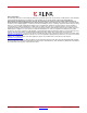
CRC Masking X-Ref Target - Figure 8-1 LUT6 LUT6 LUT6 LUT6 LUT6 LUT6 Segments of four frames shown passing through the LUTs of the two SLICEMs within a CLB SLICEM Frames LUT6 LUT6 16 CLBs SLICEX Frames SLICEM SLICEL SLICEX CLB CLB UG380_c8_01_052412 Figure 8-1: CLB Frame Masking with Distributed RAM There are two types of CLBs, those containing SLICEM, which are able to configure as distributed RAM, and those containing SLICEL, which cannot.
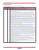
Chapter 8: Readback CRC CLBs Near Top or Bottom IOI Using DRP Using IOI with DRP requires additional masking because the IOI configuration data is now reconfigurable during user operation. The organization of the IOI data in frames also encompasses the 14 adjacent CLBs shown in Figure 8-2.
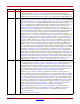
CRC Masking CLBs Near Top or Bottom IOI DRP with LUTs Configured as Distributed RAM Using IOI with DRP in addition to LUTs configured as distributed RAM results in masking that is a combination of the two scenarios above and results in five frames being masked, as shown in Figure 8-3.
Chapter 8: Readback CRC Because JTAG has the highest priority in the configuration mode, it takes over the configuration bus whenever it needs to. The JTAG Instruction Register must not be parked at the CFG_IN, CFG_OUT, or ISC_ENABLE instructions. Post_CRC Constraints There are several Spartan-6 FPGA constraints used for signaling SEU events. All constraints have the same propagation rule. They are placed as an attribute on the CONFIG block, then propagated to the physical design object.
Post_CRC Constraints • PRE_COMPUTED BitGen calculates the CRC value and stores it in the FPGA. All CRC checks are compared against this value (default). • FIRST_READBACK After successful configuration, the CRC logic runs in the FPGA and stores the first calculated CRC value. All subsequent CRC checks are compared against this value. POST_CRC_ACTION POST_CRC_ACTION determines the behavior of the Readback CRC feature after a CRC error is detected.
Chapter 8: Readback CRC POST_CRC_ACTION UCF Syntax Example CONFIG POST_CRC_ACTION = [HALT|CONTINUE] POST_CRC_FREQ UCF Syntax Example CONFIG POST_CRC_FREQ = [2|4|6|10|12|16|22|26|33|40|50] 144 www.xilinx.com Spartan-6 FPGA Configuration User Guide UG380 (v2.
Chapter 9 Advanced Configuration Interfaces Serial Daisy-Chains Multiple Spartan®-6 devices can be configured from a single configuration source by arranging the devices in a serial daisy-chain. In a serial daisy-chain, devices receive their configuration data through their DIN pin, passing configuration data along to downstream devices through their DOUT pin.
Chapter 9: Advanced Configuration Interfaces 3. The BitGen startup clock setting must be set for CCLK for serial configuration. 4. The PROM in this diagram represents one or more Xilinx® PROMs. Multiple Xilinx PROMs can be cascaded to increase the overall configuration storage capacity. 5. The BIT file must be reformatted into a PROM file before it can be stored on the Xilinx PROM. 6. The CCLK net requires Thevenin parallel termination. See Board Layout for Configuration Clock (CCLK), page 54. 7.
Ganged Serial Configuration Table 9-1: Maximum Number of Configuration Bits, Various Device Families Architecture Spartan-6, Spartan-3, Virtex-6, Virtex-5, Virtex-4, Virtex-II Pro, and Virtex-II Devices Virtex, Virtex-E, Spartan-II, and Spartan-IIE Devices Maximum DOUT Bits 32 x (227 – 1) = 4,294,967,264 32 x (220 – 1) = 33,554,216 Guidelines and Design Considerations for Serial Daisy-Chains There are a number of important considerations for serial daisy-chains: Startup Sequencing (GTS) GTS should be
Chapter 9: Advanced Configuration Interfaces typically set for Master Serial mode (to drive CCLK) while the others are set for Slave Serial mode. For ganged serial configuration, all devices must be identical. Configuration can be driven from a configuration PROM or from an external configuration controller.
Multiple Device SelectMAP Configuration 9. Ganged serial configuration is specific to the Platform Flash (XCFxxS and XCFxxP) PROMs and SPI serial flash only. 10. Fallback MultiBoot is not supported in this configuration. There are a number of important considerations for ganged serial configuration: • Startup sequencing (GTS) GTS should be released before DONE or during the same cycle as DONE to ensure all devices are operational when all DONE pins have been released.
Chapter 9: Advanced Configuration Interfaces If Readback is going to be performed on the device after configuration, the RDWR_B and BUSY signals must be handled appropriately. (For details, refer to Chapter 6, Readback and Configuration Verification.) Otherwise, RDWR_B can be tied Low and BUSY can be ignored. The BUSY signal never needs to be monitored when configuring Spartan-6 devices. Refer to Bitstream Loading (Steps 4-7), page 83 and to Chapter 6, Readback and Configuration Verification.
Parallel Daisy-Chain Parallel Daisy-Chain Spartan-6 FPGA configuration supports parallel daisy-chains. Figure 9-4 shows an example schematic of the leading device in Master BPI configuration mode. The leading device can also be in Master or Slave SelectMAP modes. The D[15:0], CCLK, RDWR_B, PROGRAM_B, DONE, and INIT_B pins share a common connection between all of the devices. The CSI_B pins are daisy-chained, gating the configuration data to each device in sequence.
Chapter 9: Advanced Configuration Interfaces Ganged SelectMAP It is also possible to configure simultaneously multiple devices with the same configuration bitstream by using a ganged SelectMAP configuration. In a ganged SelectMAP arrangement, the CSI_B pins of two or more devices are connected together (or tied to ground), causing all devices to recognize data presented on the D pins.
SelectMAP ABORT 7. The Xilinx PROM must be set for parallel mode. This mode is available on the XCFxxP devices. 8. When configuring a Spartan-6 device in SelectMAP mode from a Xilinx configuration PROM, the RDWR_B and CSI_B signals can be tied Low (see SelectMAP Data Loading, page 35). 9. Ganged SelectMAP configuration is specific to the Platform Flash XCFxxP PROM. 10. The CCLK net requires Thevenin parallel termination. See Board Layout for Configuration Clock (CCLK), page 54.
Chapter 9: Advanced Configuration Interfaces Readback Abort Sequence Description An ABORT is signaled during readback as follows: 1. The readback sequence begins normally. 2. The user pulls the RDWR_B pin Low while the device is selected (CSI_B asserted Low). 3. BUSY goes High if CSI_B remains asserted (Low). 4. The ABORT ends when CSI_B is deasserted.
SelectMAP Reconfiguration Table 9-2: ABORT Status Word (Cont’d) Bit Number Status Bit Name D4 IN_ABORT_B D3-D0 1111 Meaning ABORT in progress (active Low) 0 = Abort is in progress. 1 = No abort in progress. Fixed to ones. The ABORT sequence lasts four CCLK cycles. During those cycles, the status word changes to reflect data alignment and ABORT status.
Chapter 9: Advanced Configuration Interfaces 156 www.xilinx.com Spartan-6 FPGA Configuration User Guide UG380 (v2.
Chapter 10 Advanced JTAG Configurations Introduction Spartan®-6 devices support IEEE Std 1149.1. The Joint Test Action Group (JTAG) is the technical subcommittee responsible for developing IEEE Std 1149.1. This standard ensures the board-level integrity of individual components and the interconnections between them. The IEEE Std 1149.1 TAP and boundary-scan architecture is commonly referred to as JTAG.
Chapter 10: Advanced JTAG Configurations JTAG Configuration/Readback TAP Controller and Architecture The Spartan-6 FPGA TAP contains four mandatory dedicated pins as specified by the protocol given in Table 3-1 and illustrated in Figure 10-1, a typical JTAG architecture. X-Ref Target - Figure 10-1 IEEE Standard 1149.
JTAG Configuration/Readback The operation of each state is described here: Test-Logic-Reset: All test logic is disabled in this controller state, enabling the normal operation of the IC. The TAP controller state machine is designed so that regardless of the initial state of the controller, the Test-Logic-Reset state can be entered by holding TMS High and pulsing TCK five times. Consequently, the Test Reset (TRST) pin is optional and not found on Xilinx® devices.
Chapter 10: Advanced JTAG Configurations X-Ref Target - Figure 10-2 1 TEST-LOGIC-RESET 0 0 RUN-TEST/IDLE 1 SELECT-DR-SCAN 1 1 0 SELECT-IR-SCAN 1 CAPTURE-DR 0 CAPTURE-IR 0 0 0 SHIFT-DR 1 EXIT1-DR 1 1 EXIT1-IR 0 0 PAUSE-DR PAUSE-IR 0 0 1 1 EXIT2-DR 0 EXIT2-IR 1 1 UPDATE-DR 1 0 SHIFT-IR 1 0 1 0 UPDATE-IR 1 0 Note: The value shown adjacent to each state transition represents the signal present at TMS at the time of a rising edge at TCK.
JTAG Configuration/Readback 3. Overwrite the FPGA configuration with a design that does not use inversion at the inputs. 4. Modify the original design to avoid the IOB invert path. JSTART and JSHUTDOWN are instructions specific to the Spartan-6 architecture and configuration flow. In Spartan-6 devices, the TAP controller is not reset by the PROGRAM_B pin and can only be reset by bringing the controller to the TLR state. The TAP controller is reset on power up.
Chapter 10: Advanced JTAG Configurations Internal pull-up and pull-down resistors should be considered when test vectors are being developed for testing opens and shorts. The HSWAPEN pin determines whether the IOB has a pull-up resistor. Figure 10-3 is a representation of Spartan-6 FPGA boundary-scan architecture. X-Ref Target - Figure 10-3 TDI 1x 01 00 D Q D sd Q LE INTEST 1 IOB.I 0 1x 01 00 D Q D sd Q LE 1 0 IOB.O IOB.
JTAG Configuration/Readback To invoke an operation, the desired opcode must be loaded into the Instruction Register (IR). The length of the instruction register varies by device type. However, the IR is 6 bits wide for all Spartan-6 FPGAs. Table 10-2: Spartan-6 FPGA Boundary-Scan Instructions Boundary-Scan Command Instruction EXTEST 001111 Enables boundary-scan EXTEST operation. SAMPLE 000001 Enables boundary-scan SAMPLE operation. USER1 000010 Access user-defined register 1.
Chapter 10: Advanced JTAG Configurations Table 10-3 shows the instruction capture values loaded into the IR as part of an instruction scan sequence. Table 10-3: TDI → Instruction Capture Values IR[5] IR[4] IR[3] IR[2] IR[1:0] DONE INIT(1) ISC_ENABLED ISC_DONE 01 → TDO BYPASS Register The other standard data register is the single flip-flop BYPASS register. It passes data serially from the TDI pin to the TDO pin during a bypass instruction.
JTAG Configuration/Readback Using Boundary-Scan in Spartan-6 Devices Characterization data for some of the most commonly requested timing parameters shown in Figure 10-4 is listed in the Spartan-6 FPGA Data Sheet: DC and Switching Characteristics in the Configuration Switching Characteristics table.
Chapter 10: Advanced JTAG Configurations X-Ref Target - Figure 10-5 Power-Up No VCCINT > .
JTAG Configuration/Readback Single Device Configuration Table 10-4 describes the TAP controller commands required to configure a Spartan-6 device. Refer to Figure 10-2 for TAP controller states. These TAP controller commands are issued automatically if configuring the part with the iMPACT software. Table 10-4: Single Device Configuration Sequence Set and Hold # of Clocks TAP Controller Step and Description TDI TMS TCK 1. On power-up, place a logic 1 on the TMS, and clock the TCK five times.
Chapter 10: Advanced JTAG Configurations Multiple Device Configuration It is possible to configure multiple Spartan-6 devices in a chain. (See Figure 10-6.) The devices in the JTAG chain are configured one at a time. The multiple device configuration steps can be applied to any size chain. Refer to the state diagram in Figure 10-1 for the following TAP controller steps: 1. On power-up, place a logic 1 on the TMS and clock the TCK five times. This ensures starting in the TLR (Test-Logic-Reset) state. 2.
JTAG Configuration/Readback When the shutdown sequence is clocked by CCLK or UserCLK, the user is responsible for knowing how many JTAGCLK cycles in Run/Test Idle are needed to complete the shutdown sequence. The shutdown sequence is the startup sequence in reverse order. Note: When configuring the device through JTAG, the startup and shutdown clock should come from TCK, regardless of the selection in BitGen. Spartan-6 FPGA Configuration User Guide UG380 (v2.7) October 29, 2014 www.xilinx.
Chapter 10: Advanced JTAG Configurations 170 www.xilinx.com Spartan-6 FPGA Configuration User Guide UG380 (v2.