
Instruction manual
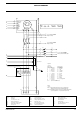
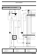
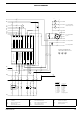
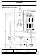
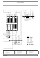
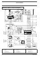
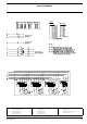
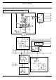
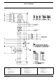


CIRCUIT DIAGRAM
2954 2370 00 65
K6 Fuel solenoid relay (S2b: see Power Circuit) V2 Diode
M1
Starter motor
S6 Low coolant level switch X10 Connector wire harness
M6 Fuel feed pump S8 High coolant temperature switch X25 Customer’s terminal strip
R2 Excitat. resistor 47 Ohm S9 Low oil pressure switch Y1 Fuel stop solenoid
S2a Emergency stop S20 ON/OFF-switch
Sx
Fx FxFx Fx
Fx
17
a2
b1
K1
e4
K6
Position of Relay Cont.
b3
K5
e5
K4
2
2
2
2
2
2
2
2
2
Wire size : Colour code :
Legend
aa = 0.5mm
a = 1 mm
b = 1.5mm
c = 2.5mm
d = 4 mm
e = 6 mm
f = 10 mm
g = 16 mm
j = 50 mm
0 = black
2 = red
3 = orange
4 = yellow
5 = green
6 = blue
7 = purple
8 = grey
54= green/yellow
9
a3
10
a3
11
a3
9
a3
11
a3
10
a3
B9B8
12
a6
to X25.10
PE
X25
987 10
X25
3 65421
PE
Customer's Installation
(see Instruction Manual)
MAINS SUPPLY (3P+N+PE)
Sx=Remote
Start/Stop-switch
to Plant Contactor A2 <--
to Plant Contactor A1 <--
to Mains Contactor A1 <--
L3L2L1L1N
to BATT-
to A1.37
to Circ.Diagr POWER
Fuses F1-F3
250mA 250mA6A 250mA
to Circ.Diagr POWER
X9.441 & X9.442
12
a6
18
a3
6A
124
a6
442
b0
441
b6
443
a0
447
a0
446
a0
445
a0
442
a0
444
a0
12
a6
12
a6
4
a3
12
a6
12
a6
12
a6
14
a3
14
a3
12
a6
12
a6
B4
B4
X10
B5
B5
X10
C3
C3
X10
A4
A4
X10
C1
C1
X10
C2
C2
X10
K1
4
a3
14
a3
K6 K5
+
-
A
B7
D
C
142
c8
141
c8
151
c8
143
c8
125
a0
127
a0
126
a0
12
a6
25
a3
15
a3
17
a2
Relay Output 1
21
31
NO
Input
Com
NO
NO
Relay Output 3
Relay Output 2
NO
Common for Relay Outputs
4633
Central Alarm Horn
Common for VDO-inputs (0 Vdc)
4532
Preheat Relay
4430 434229
Com
Magnetic Pick-up (Tacho)
41
Input
Coolant Temp (VDO)
Common for CT-inputs
Oil Pressure (VDO)
Fuel Level (VDO)
Input
Input
16 23352234
NO
Com
NO
Com
NO
17 36
s2
s1
s1
s1
Generator Current Transfo L3
Generator Current Transfo L2
Generator Voltage L3
Generator Voltage L1
Generator Voltage L2
Generator Current Transfo L1
Common (12 Vdc)
Start Relay Output
Fuel Control Relay
Generator Voltage Neutral
2018151412 19
A
B
C
D
E
F
G
H
N