
Instruction manual
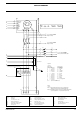
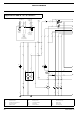
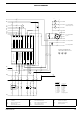
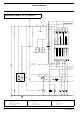
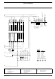
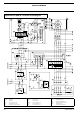
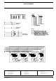
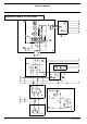
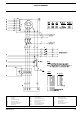


CIRCUIT DIAGRAM
62 2954 2370 00
A1 Generator control unit F4 Fuse 10 A K1 Preheat relay
B7 Fuel level sensor G1 Battery 12 Vdc K4 W/L-invertor relay
B8 Coolant temperature sensor G2 Charging alternator K5 Starter relay
B9 Oil pressure sensor H1 Panel light M1 Starter motor
E1 Preheat resistor K0 Starter solenoid M6 Fuel feed pump
Sx
Fx
Fx
a2
17
a3
8
c2
3
16
e2
R2
V2
W
D+
GND
B+
G2
a6
12
c3
3
a6
12
K4
a3
8
a3
8
S6
a3
5
(*)= Connect L2 to X25.1
with 230Vd-systems
Plant Contactor
Output: 12Vdc,
max. 8Adc1
(*)
Customer's Installation
(see Instruction Manual)
N
3
X25
to Control Module A1
1
X25
6
X25
42 5
MAINS SUPPLY
Sx=Remote
Start/Stop-switch
max. 24Vdc, 4A
to Plant Contactor A2 <--
to Plant Contactor A1 <--
L1
6A
to Circ.Diagr POWER
X9.441 & X9.442
19
a3
18
a3
6A
12
a6
442
b0
441
b6
38
a0
c2
1
c2
1
a6
12
a3
15
a6
12
a6
12
a6
12
a3
7
a3
6
a3
6
a3
7
K5
S20
c2
13
10A
F4
K5
2
a3
K4
B3
B3
X10
Cubicle
Canopy
A3 A3
X10
Cubicle
Canopy
B1
B1
X10
B2
B2
X10
A1 A1
X10
A2
A2
X10
K0
K0
M
M1
E1
K1
P
S9
e2
1
j6
12
e2
1
16
e2
G1
-
+
a6
12
a3
7
a3
6
a3
2
e2
1
e2
1
j0
1
j0
1
c2
3
j6
12
S8
A
B
C
D
E
F
G
H
K
L
M
N
J
2
9822 0992 18/01
Applicable for QAS 30 - 45 - 60 Qc1001™