
Instruction manual
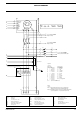
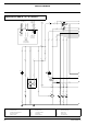
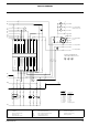
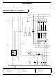
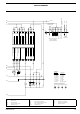
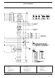


CIRCUIT DIAGRAM
2954 2370 00 61
B11 Speed sensor MPU (O)
Q1 Circuit breaker T13 Torus earth leakage (O)
F1-F3 Fuses 4 A
R5 Coolant heater (O) U1 Battery charger (O)
G3 Alternator R11 Speed adjustment 5 K (O) V7 Free-wheeling diode Y7
K7 Aux. relay for Y7 (O)
R12 Voltage adjustment 1 K (O) X1 Terminal board
N11 Speed controller (O)
S2b Emergency stop
X9 Terminal strip
N12 Automatic voltage regulator
(S2a: see Engine Circuit)
Y7 Air inlet shutdown valve (O)
N13 Earth leakage relay (O) S13 E.L.R. Disable-switch (O)
(O) Optional equipment
N14 IT-relay (O)
T1-T3 Current transformers
b0
.F2
b0
.F1
b0
.Z2
bx0
.7
bx0
.8
c8
141
c8
142
c8
151
a0
U1
a0
V1
a0
W1
a6
C
g54
y54y54
c2
c1
U>
I >> I >> I >>
a0
125
a0
126
a0
127
a6
124
y54y6
C
C
Q1
T13
PE
X1
L1 L2 L3 PE
See Note 1
N
F3
F2
F1
x0
W1
x0
V1
x0
U1
c8
143
to Circ. Diagr ENGINE
Ampere-meter
QAS
30
T1
100/5A
Q1
80A
Wire Size x
25mm†
Wire Size y
16mm†
to Circ. Diagr ENGINE
Ampere-meter
to Circ. Diagr ENGINE
V-meter & Control Module
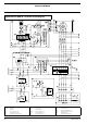
Notes
Note 1: The PE-N connection has to be made at the
alternator-side of main Circuit Breaker Q1.
Note 2: Link N12.1 to N12.2 on gen-sets without Electronic
Speed Regulation (= no potentiometer R12).
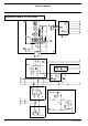
G3
W6
W5
W2
W1
U1
U2
U5
U6
V6 V5
230V 50Hz
V2 V1
XX (F2)
X+(F1)
Z2
V5
U5
U1
U1
V1
U1
C
PE
V1
T1 T2 T3
W1 V6
A
B
C
D
E
F
G
H
I
J
K
L
M
Cubicle
Canopy
1
2
y54
PE
x0
L3
x0
L2
x0
L1
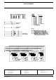
Legend
Wire size :
aa = 0.5 mm†
a = 1 mm†
b = 1.5 mm†
c = 2.5 mm†
d = 4 mm†
e = 6 mm†
f = 10 mm†
g = 16 mm†
h = 25 mm†
i = 35 mm†
j = 50 mm†
k = 70 mm†
bx = 1.5 mm† NSGAFOeU
Colour code :
0 = black
1 = brown
2 = red
3 = orange
4 = yellow
5 = green
6 = blue
7 = purple
8 = grey
9 = white
54 = green/yellow