
Instruction manual

Instruction manual
2954 2370 00 11
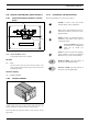
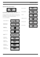
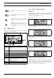
2.6 Control and indicator panel Qc1001™
2.6.1 General description Qc1001™ control
panel
H1......Panel light
S20 ....ON/OFF/REMOTE switch
To start up the unit (locally or remote).
DC-Fuse
F4 ......Fuse
The fuse activates when the current from the battery to the
engine control circuit exceeds its setting. The fuse can be reset
by pushing the button.
Qc1001™ display
A1......Qc1001™
display
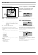
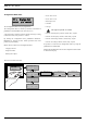
2.6.2 Qc1001™ Module
The Qc1001™ module is located inside the control panel. This
control module will carry out all necessary tasks to control and
protect a generator, regardless of the use of the generator.
This means that the Qc1001™ module can be used for several
applications.
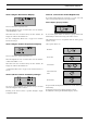
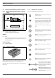
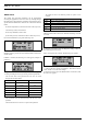
2.6.3 Pushbutton and LED functions
Following pushbuttons are used on the Qc1001™:
0
10
30
20
0
10
30
20
0
10
30
20
0
400
200
www.atlascopco.com
!
Qc 1001
Appl. 1.00.1
F4
R11 R12
S20
A1
P1 P2 P3 P4
S4
S20
F4A1
H1
ENTER: Is used to select and confirm
changed settings in the Configuration.
UP: Is used to scroll through the display in-
formation. This button is also active in Con-
figuration Mode.
DOWN: Is used to scroll through the display
information. This button is also active in
Configuration Mode.
When UP & DOWN are pressed at
the same time for 3s, Configuration
Mode will be entered (see
page 16).
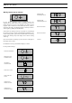
BACK: Is used to leave/enter the Warnings
pop-up window, to leave the Configuration
Mode and to leave menu's without change.
REMOTE MODE: The LED indicates if
the gen-set is put in Remote Mode.
MANUAL MODE: The LED indicates if
the gen-set is put in Manual Mode.
!