MANUAL TRANSMISSION REMOTE STARTER AS-1785 Installation Guide Notice The manufacturer will accept no responsibility for any electrical damage resulting from improper installation of the product, be that either damage to the vehicle itself or to the Unit. This Unit must be installed by a certified technician using all safety devices supplied. Please note that this guide has been written for properly trained Autostart technicians: a certain level of skills and knowledge is therefore assumed.
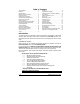
Table of Contents Table of Contents....................................................... 2 Introduction ................................................................ 2 Included in the Kit....................................................... 2 Installation Points to Remember................................ 3 Harness Description................................................... 4 Flashing the Hood Pin Switch.................................. 11 The Programming Assistance Button ......................
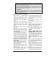
Operation is subject to the following two conditions: (1) this device may not cause interference, and (2) this device must accept any interference, including interference that may cause undesired operation of the device. To reduce potential radio interference to other users, the antenna type and its gain should be so chosen that the equivalent isotropically radiated power (EIRP) is not more than that required for successful communication.
♦ On vehicles equipped with daytime running lights, the installer may be unable to see certain programming results since the daytime running lights never go out. Note: The Parking Light Output Relay of the unit gives two clicking sounds for each flash of the lights: one click when the lights would go ON and one click when the lights would go OFF.) ♦ Parking Light flashes to which the text refers throughout this manual refer to the Parking Light output of the unit, not of the vehicle.
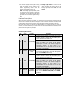
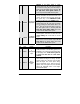
E ORANGE (+) Accessories output (30 A) F GREEN (+) Fifth Relay output (30 A) Warning: at the Ignition Switch of certain vehicles, there may be more than one Ignition wire. Use the 5th relay (Pin F) and extra relays to power up any extra Ignition wires if necessary. Do not jump wires at the Ignition Switch: this would compromise the OEM electrical system. This wire will power the Heater Blower Motor. Usually connected to the Accessories wire of the vehicle.
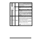
3 GREY (–) Hood Switch input 4 ORANGE (+) Brake Switch input 5 YELLOW (+) 12 V Parking Light output Note: if the Tach signal is too low, the Remote Car Starter will “over-crank”. Conversely, if the Tach signal is too high, the Remote Car Starter will “under-crank”. Connect this wire to the installed Hood Pin switch supplied. This input will disable or shut down the Remote Starter when the Hood is up. This wire must be connected to the Brake Light wire of the vehicle.
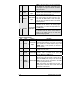
5 WHITE / GREEN (–) Disarm output 6 BLUE / WHITE (+) Positive Door input 7 WHITE / ORANGE (–) Starter Kill output (armed output) 8 ORANGE 500 mA ground pulse when the Doors are unlocked by remote control. Connect to the OEM Disarm wire of the vehicle. Note: The system will also give a Disarm pulse on this wire before every remote start. This input should be used in vehicles with positiveswitching Door pins or Dome Light circuits.
9 10 P. 8 PURPLE WHITE (–) External Trigger (–) Ground Out When Running The External Trigger wire can be used for remotestarting the vehicle with an external device. When the vehicle is running, triggering this input will activate Idle Mode. The External Trigger wire can also be used to operate as a negative trigger with the Trunk Pin-switch, the Key Sense wire or the Door Pin-switch: Option 1 Connects to Negative Trunk Pin.
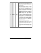
11 GREY 12 YELLOW Caution! If multiple relays or modules are connected to the GROUND OUT WHEN RUNNING wire, make sure they are diode isolated from one another: feedback may otherwise occur, causing damage to the vehicle. This input should be used in vehicles with negativeswitching Door pins or Dome Light circuits. Connect to the Dome Light wire that tests ground when a Door is open. Caution! The installer should use either the positive (–) Negative Door or the negative Door input.
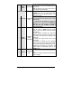
12 P. 10 YELLOW (+) Glow-Plug input (cont.) (Also known as the “wait-to-start light”.) The purpose of the Glow-plug circuit on diesel vehicles is to pre-heat the Combustion Chamber before the vehicle is started. When a Remote Starter is installed on a diesel vehicle, the Glow-plug section of the Ignition circuit must be activated and allowed to operate before the vehicle is remote-started.
12 YELLOW (+) Glow-Plug input (cont.) o Minimum waiting time is 3 seconds. o Maximum waiting time is 18 seconds. If no Glow-plug wire is found on the vehicle, the Glow-plug input on the Remote Car Starter may be “timed out”. The Remote Car Starter will power up the Ignition and Glow-plug circuits and simply wait for the time-out before starting: • Connecting the Glow-plug input wire of the Remote Car Starter to Ignition will hold the ignition ON for the maximum waiting time (18 sec., recommended).
Here are the steps which the installer must follow in order to flash the Hood Pin switch: The Installer … The Module … Press and hold the Hood Pin switch for 4 seconds. Release the Hood Pin switch. The Parking Lights will turn ON. While the Parking Lights are ON, press down the Hood Pin switch once more. Release the Hood Pin switch again.
memory, you must perform a reset of the Remote Car Starter (see Resetting the Remote Car Starter, later in this Guide, for more details). The Transmitter Programming Procedure 1. Flash the Hood Pin switch (see Table 1) – The Parking Lights will stay ON for up to 20 seconds. – Before the lights go out, turn the Ignition Key to the IGNITION ON (RUN) position. – Immediately turn the Ignition Key back to the OFF position. 2.
Table 4: Accessing options In each Function, once an Option has been selected the Parking Lights will flash 1, 2, 3 or 4 times (depending on the selected Option). Please note that the different Functions within any particular Mode can only be accessed sequentially: the Programming Centre will move from Function 1 to Function 2, then to Function 3, and so on. Therefore, whenever you access a particular Mode, be prepared to re-configure all the Functions of that Mode in ascending order.
FUNCTION 3 – Turbo Mode OPTION 1 OPTION 2* OPTION 3 Turbo Mode ENABLED Turbo Mode DISABLED Turbo Mode ENABLED FUNCTION 4 – Engine type and Cold Weather Mode OPTION 1 OPTION 2* OPTION 3 Diesel Mode with 20-minute Run Time in Cold Weather Mode Gas Mode with 4-minute Run Time in Cold Weather Mode Diesel Mode with 9-minute Run Time in Cold Weather Mode FUNCTION 5 – Ignition Valet OPTION 1 OPTION 2* OPTION 3 Ignition Valet DISABLED Ignition Valet ENABLED Ignition Valet ENABLED MODE 3 * INDICATES DEFAULT S
adjustment. Nevertheless, a Tach-programming procedure must be carried out every time a new Remote Car Starter Unit is installed. This is because the Tach signals of certain Ignition systems are sometimes too low or too high for the Remote Car Starter, causing failed start-ups at various temperatures. 1. Flash the Hood Pin switch (see Table 1) – The Parking Lights will stay ON for up to 20 seconds. – Before the lights go out: 2.
a. To increase the Horn pulse by 3 ms, press the LOCK button. b. To decrease the pulse by 3 ms, press the UNLOCK button. c. To increase the pulse by 10 ms, press the START or STOP button. d. To decrease the pulse by 10 ms, press the TRUNK button. 5. To save the new settings: press LOCK and UNLOCK. If 3 honks are returned the new settings have been saved. Table 9: Adjusting Honk Duration Otherwise close the Hood to cancel the changes.
Remaining in ready Mode Once the vehicle is in Ready Mode, you can start and stop the vehicle at wish. However, should any one of the following occur, the vehicle will exit Ready Mode, thus disabling remote start capabilities until Ready Mode is restored: • Door opened, • Hood opened, • Brake pedal pressed, • Parking Brake disengaged, • Ignition Key turned to the IGNITION ON (IGNITION ON / RUN) position. Should any of the above occur, Ready Mode will be cancelled.
Most comebacks are the result of misunderstandings about how a product works or performs. Take the time to properly explain all functions and features to the customers before they leave the premises. Doing this will save time and money. Always make all your connections before plugging in the Remote Car Starter, and be sure to test all functions properly before closing up the installation. Make sure the Warning Label is applied on a visible place under the Hood.
test the wire with the Key in the START position With the pedal down: test the wire with the Ignition Key in the OFF position test the wire with the Key in the IGNITION ON (RUN) position test the wire with the Key in the START position With this information for every wire at the switch, determining what type of clutch switching system you have will be easy. Direct Feed: The simplest type of system to test and bypass is the “Direct Feed” system.
Note on N/C systems: There are different types of this system used by various vehicle manufactures, the following is used to illustrate how these systems work in general. Normally Closed (N/C) Systems: In the previous two examples, the clutch was bypassed by engaging the clutch relay. In an N/C system, a relay is also used to interrupt the starter wire. In order to bypass an N/C Clutch, one must prevent the Clutch relay from engaging.
If the vehicle is initially unlocked, upon remote START the Remote Car Starter will start the Engine and arm the Starter Kill, but the Doors will not be locked or unlocked at any moment of the sequence. Lock Pulse Duration The duration of the Lock and Unlock pulses can be configured as follows: • (Default) 7/10-sec. LOCK and 7/10-sec. UNLOCK pulses • 4-sec. LOCK/UNLOCK pulses to control vacuum Door Lock systems • A single 7/10-sec. LOCK pulse and two 1/4-sec.
2. Press and release the Break Pedal 6 times (within 10 seconds from entering Programming Mode). 3. The Parking Lights will flash 8 times to confirm resetting. Table 10: Resetting without a Valet Button On some vehicles (such as BMW and certain Volkswagen vehicles), resetting will not work if the Brake Pedal is pressed while the Ignition Key is not in the IGNITION ON (RUN) position: you will need therefore to hot-wire the Brake Pedal by manually jumping 12 V with a fused test lead at the Brake Pedal switch.
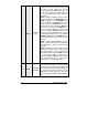
Diagnostics – Parking Light Flash Table Flashes 1 2 3 4 5 6 8 10 1 – pause – 2 2 – pause – 2 Description • • • • • • • • • • • • • • • • • • • • 4 – pause – 3 • 10 – pause – 3 • • ON 2 sec. ON 3 sec. ON 4 sec. • • • ON 25 sec. • Irregular Constant flashes up to 30 sec. P. 24 Doors locked, Starter Kill armed. End of Run Time. TRUNK button pressed Start signal received by the Remote Car Starter. Cold Weather Mode cancelled. Cannot start after maximum number of attempts is reached.