
Installation manual


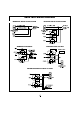

Main Harness:
• GREEN/WHITE WIRE - Brake switch input
wire. Connect this wire to the brake switch
wire that provides +12V when the brake pedal
is pressed. This is a safety input and must be
connected on all installations.
• BLACK/GRAY WIRE - Tachometer input. If
the Smart Start feature fails to start properly,
connect the BLACK/GRAY wire directly to the
vehicle’s tach wire or negative fuel injector wire,
and program Step #14 to Tach Start.
• WHITE/RED WIRE - Auxiliary 2 output (-)
500mA. Connect to a relay or module for an
optional feature such as power window
activation, etc.This output may be programmed
for momentary, timed, or latched operation.
• BLACK/WHITE WIRE - Dome Light output (-
) 500mA. Connect to a relay to activate the
vehicle’s dome light. NOTE: The dome light
relay’s output is usually connected to the same
wire used for the door trigger input (See
GREEN and VIOLET door trigger wires).
• YELLOW WIRE - +12V Ignition input.
Connect to a main ignition wire at the ignition
switch harness.This wire shows +12V when the
ignition is on and while cranking. The voltage
must not drop when the car is starting.
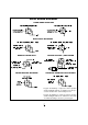
• BLUE/YELLOW WIRE - Glow Plug input (+).
For diesel engines connect to the glow plug wire
in the instrument cluster that shows +12V when
the the glow plug (wait-to-start) light is on, then
shows ground when the light turns off. For
vehicle’s equipped with a negative glow plug
wire (shows ground when the wait-to-start light
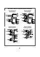
is on) a relay is required. (see Relay Diagrams)
• BLUE/WHITE WIRE - Passenger Unlock
output (-) 500mA. Connect to an optional relay
to unlock the passenger doors when the system
is configured for Driver Priority Unlocking.
• BLUE/ORANGE WIRE - Ground When
Running Output (-). This wire provides a ground
when the remote start is engaged to activate an
optional factory security bypass module.
• BLACK WIRE - Ground input (-). Connect to
a solid chassis ground that is clean and free of
paint or dirt.
• RED WIRE - +12V Battery input #3. Connect
the red fused wire on the main harness to a
constant +12V source. This wire is the power
input for the module.
• VIOLET WIRE - Positive door trigger (+).
Connect to the door switch circuit wire that
shows +12V when the door is open. This type
of door circuit is usually found on Ford vehicles.
• GREEN WIRE - Negative door trigger (-).
Connect to the door switch circuit wire that
shows ground when the door is open.
• WHITE/BLACK WIRE - Hood switch input
wire (-). Connect this wire to the hood pin
switch to prevent the vehicle from starting if the
hood is open.This is a safety input and must be
connected on all installations.
• ORANGE WIRE - Locked output (-) 500mA.
Connect to a relay for optional starter defeat
and anti-grind protection. (See Relay Diagrams).
• VIOLET/WHITE WIRE - Factory Disarm
output (-). Connect to the wire that requires a
ground pulse to disarm the factory alarm. The
VIOLET/WHITE wire provides a ground pulse
when the remote transmitter is used to unlock
the doors or start the vehicle.
• WHITE/VIOLET WIRE - Factory Arm
output (-). Connect to the wire that requires a
ground pulse to arm the factory alarm. The
WHITE/VIOLET wire provides a ground pulse
when the remote start shuts down.
• BROWN WIRE - Audible status output (+) 3A.
Connect an optional siren for lock/unlock chirps.
2