AUTOMATIC TRANSMISSION REMOTE STARTER SYSTEM CT-5000 Installation Guide Notice The manufacturer will accept no responsibility for any electrical damage resulting from improper installation of the product, be that either damage to the vehicle itself or to the Unit. This Unit must be installed by a certified technician using all safety devices supplied. Please note that this guide has been written for properly trained Autostart technicians, a certain level of skill and knowledge is therefore assumed.
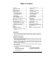
Table of Contents Introduction ..................................................... 2 Included in the Package ................................. 2 Installation Tools:............................................ 3 Before You Get Started…............................... 3 Harness Description ....................................... 4 6-Pin Main Ignition Harness ....................... 4 5-Pin Secondary Harness........................... 5 12-Pin Accessories Harness ...................... 6 2-Pin Harness .......
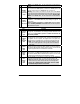
1 – six-pin 14 AWG Harness (Ignition Harness) 1 – five-pin 18 AWG Harness (Main Harness) 1 – twelve-pin 22 AWG Harness (Accessories Harness) 1– 1– 1– 1– two-pin 22 AWG Harness (Accessories Harness) five-pin Harness (Data Port Harness) Parts bag: a Hood Pin-switch, a connector, wires and a warning label User Guide. Installation Tools: Here is a list of basic tools and supplies you will need to test and install safely.
♦ Make sure that all safety equipment is installed: the Valet Button, the Hood Switch and the warning label ♦ When wiring in parallel, make sure to isolate each connection with a diode in order to avoid feedback and possible damage. Examples: Wiring a clutch bypass and a Transponder Module to the Ground Out when Running wire: At the junction point, where Ground Out when running “splits” and goes to each device, a diode is inserted on each of those lines.
WIRES at the IGNITION switch, this will compromise the OEM electrical system. This wire is for powering the heater blower motor. It is usually classed as an ACC. (no power in the CRANK position.) if it tests as an IGNITION (power in the crank pos.) then power it as an IGNITION (5th relay, or extra fuse). ORANGE Warning: some vehicles have more than one ACC wire at the IGNITION (+) 30 A E Accessories switch for powering the heater blower motor.
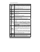
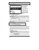
12-Pin Accessories Harness Wire Description 500 mA negative output. This output can be used to control Trunk release (1-sec. pulse) or can be set to operate as a constant output as long as the TRUNK button is held pressed. (For Sunroof or Window close). Note: AUX3 (TRUNK) operates only when Ignition is OFF or when the vehicle is running under remote control. 1 BLUE (–) AUX 3 (Trunk) output 2 BROWN (–) Lock output 3 GREEN (–) Unlock output Programmable 500 mA, 1/10-sec., 7/10-sec., 4-sec.
10 WHITE (–) Ground out when running 11 GRAY (–) Negative Door input This is a 500-mA constant ground output that is active when the vehicle is running under a remote start. The output becomes active at the same time as the Ignition, and becomes inactive when the Module shuts down (i.e.: runtime has expired or the START/STOP button is pressed, etc.). The output can be used to activate external relays, bypass kits, etc.
12 YELLOW (+) Glowplug Light input This positive input will monitor the Glow Plug Light in Diesel Mode: it will wait until the Glow Plug Light goes out to crank the Engine. Connect to the side of the Glow Plug Light that is positive when the Light is on. Note: In Diesel Mode there is a 18-sec. crank timing delay (or approximately 25-sec. if the run time is set to 30 min.): if the Glow Plug Light is still on after the delay expires, the Module will proceed to start the Engine.
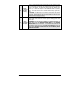
2-Pin Harness Wire Description • 500 mA negative output. Can be programmed for one of the following options: • Constant while the LOCK and UNLOCK buttons are pressed, + 1 sec. after the buttons are released. BLUE / WHITE • Pressing the LOCK + UNLOCK buttons simultaneously will toggle the AUX 2 1 ( -) AUX 2 output output ON for a 30-second cycle and shuts off automatically unless the user presses LOCK and UNLOCK before the end of that cycle, at which point, the AUX2 output shuts off.
Remember: Once the Parking Lights are on Solid, you have up to 20 seconds to select a submenu. Failure to do so will result in the Module exiting the Programming Centre and you will have to Flash the Hood Pin once more. The Programming Assistance Button (A.k.a. PAB.) The PAB is located on the side of the Module. This push button mimics the Hood-Pin switch in order to avoid having to get out of the vehicle and pressing the Hood-Pin switch. The PAB will work only when the Hood is up.
The Parking Lights and the Siren will flash and chirp once, twice or 3 times to confirm entry into a Mode. 3. Release the Brake Pedal. Table 2 The Module can only be programmed Function by Function. After selecting a Mode (from 1 to 3), you will be taken to the first Function of that Mode. After entering an Option number for Function 1, you will be automatically taken to Function 2, and so on; therefore, be ready to re-enter all option numbers for all functions of the Mode you are accessing.
OPTION 3 OPTION 4 Car Finder disabled. Constant output while pressed (press LOCK and UNLOCK) Car Finder disabled. Priority Door access on 2nd Unlock, and Car Finder enabled. • The Driver’s door unlocks upon the 1st, 3rd, 5th … pressing of the UNLOCK button. • All Doors unlock upon the 2nd , 4th, 6th … pressing of the UNLOCK button.
OPTION 2* OPTION 3 OPTION 4 Function 5 – Ignition Valet OPTION 1 OPTION 2* OPTION 3 Shock Sense - monitored / Warn Away – monitored Shock Sense - Monitored / Warn Away – ignored Shock Sense - Ignored / Warn Away – monitored Ignition Valet - DISABLED Ignition Valet - ENABLED Ignition Valet - ENABLED Horn Honk / Siren Timing (Optional) 1. FLASH the Hood Pin Switch Before the 20 seconds have passed, 2. Press and hold the Brake Pedal.
Table 5 Multi-Speed Tach Programming No manual adjustments are necessary. However, you should go through the Tach programming procedure every time a new Unit is installed. 1. FLASH the Hood Pin Switch. 2. Press and hold the Brake Pedal. • Press the LOCK and UNLOCK buttons simultaneously on the Transmitter. • The Parking Lights will flash 4 times the Horn/Siren will sound 4 times (if programmed). • Release the Brake Pedal. 3. Start the vehicle and let it to reach regular Engine-idle speed. 4.
• • • 8. 9. 10. 11. Away. A medium “tap” should trigger the Warn Away. A hard “tap” should trigger the Alarm. All vehicles are different and therefore transmit shock level differently, if you are unable to set both zones to your satisfaction, referrer to p.12 (Function 4 – Shock Sense / Warn Away ) to disable the appropriate zone(s). When the Engine is running after remote start the Shock Sensor will not trigger an Alarm condition, although it will still produce warning chirps if Warn-away is enabled.
Caution! Do not use more than one of the three sets of jumper pins simultaneously. The relay output rating on this Unit is 25A max output. Defective OEM solenoid switches can sometimes draw up to 50 or 60A, causing the 30A fuse to blow. Using a digital voltmeter, check the Starter wire for amperage when vehicle is cranking. Ignition-Controlled Door Locks • • • • Ignition Lock disabled: turns OFF the Ignition Lock feature.
Safe Start (Child Safety Mode) (OFF by default.) Requires the user presses the START/STOP button on the Transmitter twice within 3 seconds in order to start the vehicle. If the Special Safe Start Mode is selected (SWAP Start): • To start the vehicle, press the LOCK and UNLOCK buttons simultaneously. • Pressing the START/STOP button triggers AUX2. START/STOP button becomes AUX2 trigger and the AUX2 button becomes the START trigger.
Disarmed Notification This feature will notify the user when the vehicle is left disarmed after Ignition is turned off, or when the Module is disarmed after being previously armed, the opening or closing of a Door will cause the Horn or the Siren to sound once after 10 sec. to warn the user that the vehicle was left unprotected. Pressing LOCK or UNLOCK will cancel this timer. Two-Stage Disarm When the Siren is sounding, pressing UNLOCK will stop the siren – but without unlocking or disarming the vehicle.
• The Parking Lights and L.E.D. will flash the five events stored in memory. The first four playback codes are Start Failure Events, while the last playback code is an Intrusion Code. There is a pause after each event code is played back. The system will play back the most recent event first, then the second most-recent, and so on. If there are no events at all to report, the Parking Lights will give one long flash.
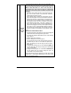
− It always better to strip more than you need, than not enough. A common way cold solder joints happen is when not enough plastic is stripped off the vehicle's wire, so during the soldering process the plastic from the wire melts and flows in to the connection instead of the solder. − Decide where the module is going to be mounted. It is ALWAYS mounted inside the passenger compartment, and never in the engine bay. Under the driver's side of the dash there is usually enough room for the module to fit.
made. This extra bit wire is wrapped around the exposed OEM wire to secure in place while you are soldering. − When all of the wires have been connected, solder the connections. When the solder has cooled, the connections are then individually taped up, to isolate them. − Return to the engine bay and route the start module wires to their corresponding connections. − Solder the engine compartment wire once the connections are made.
85 & 86: The Coil. These inputs energize the coil when one is +12 Volts, and the other is Negative. They are usually non-polarized, so it does not matter which one is positive (+) or negative (-). 87: Normally Open ( N/O). When the coil is energized, 87 is connected to 30. 87A: Normally Closed ( N/C ). When the coil is at rest, 87A is connected to 30. 30: Common. When the relay is at rest, 30 is connected to 87A, when the coil is energized, it is then moved and makes contact with 87.
Problem: You need to power Multiple Ignition wires to remote start the vehicle, but your module only has one Ignition output available. Solution: You will need to add a second ignition relay to power the second ignition wire. (Jumping Ignition 1 to Ignition 2 is NEVER recommended. Always use a relay. The vehicle circuits are Isolated for a reason, the wiring of the remote star module should reflect this.) The relay connections: 85: Connects in parallel to the Ignition 1 output from the remote start module.
Example: Activating a Positive Trunk release switch Problem: The vehicle's power trunk release switch is activated by a positive (+) pulse, and the remote start module's Trunk output is negative (-). Solution: A relay is used to invert the negative signal from the start module to a positive signal before it is sent to the OEM switch. The relay connections: 85: Connects to the start module's Trunk release output wire. This becomes the negative side of the coil. 86: Connects to a fused +12 Volts source.
86: 87: Connects to a fused +12 Volt source. Connects to a Negative source. i.e. The spot where the remote start module is grounded. This becomes the supply for activating the vehicle's Trunk release wire. 87A: No connection. This terminal is not used in this application. 30: Connects to the vehicle's Trunk release wire. Comments: At rest the relay is not active and the vehicle's Trunk release switch is allowed to operate normally.
• Are you waiting too long between programming steps? ¾ After flashing the hood pin turn the key to ON, WAIT for 2 seconds. ¾ Turn the key Off, On, Off then keep pressing the LOCK button repeatedly until you get 2. 3. 4. 5. 6. 7. 8. 9. 10. 11. 12. 13. 5 light flashes from the module. The entire process should take less than 20 seconds. The car won't start by remote.
14. The CHECK ENGINE light comes on and the vehicle doesn't shift, it feels sluggish. • Missing second ignition. (common on some GMs) 15. On cold mornings the park lights come on, go out, and then flash 2 times slowly. • Check for a weak car battery. (Try using the cold weather mode option) 16. The car doesn't start and the park lights flash 4 times. • Check brake circuit. • Check for blown rear park light (feedback). 17. The vehicle runs for 8 seconds then shuts down.
. I blow fuses every time I try the remote trunk release and I have already installed a relay. • Trunk release is reverse polarity, and not positive trigger. Chirps Chirps 1 2 3 4 5 Constant up to 30 seconds Constant up to 60 seconds P.28 Description • • • • • • • • • • • • • • • LOCK and ARM the system. LOCK confirmation. Entering Mode 1 in Programming Options. Start attempt when the Engine is already running under remote control. Disarmed Notification UNLOCK and disarm. Transmitter Programmed.
Diagnostics - Parking Lights Flash Rate Flashes 1 2 3 4 5 6 8 10 1 – pause – 2 2 – pause – 2 ON solid ON 2 sec. ON 3 sec. ON 4 sec. ON 25 sec. Irregular Constant flashes up to 30 sec. Description Doors locked, Starter Kill armed. End of Run Time. TRUNK button pressed START signal received by the Module. Cold Weather Mode cancelled. Cannot start after maximum number of attempts is reached. Run Time cancelled. Remote start attempt cancelled by remote. Doors unlocked, Starter Kill disarmed.