TWO WAY LCD AUTOMATIC TRANSMISSION REMOTE STARTER Installation Guide W A R N I N G ! This is a generic installation guide and it is designed for the specific model number stated above. Furthermore, for clarity purposes, the START/STOP button, associated with 4-button models, will be referred to as either START or STOP depending on the functionality being described.
Table of Contents Introduction ........................................................2 Included in the Kit ..............................................2 Installation Points to Remember........................3 Harness Description ..........................................4 Flashing the Hood Pin Switch............................9 The Programming Assistance Button ..............10 Programming the Transmitter..........................10 Before you proceed .........................................
INDUSTRY CANADA USER NOTICE: Operation is subject to the following two conditions: (1) this device may not cause interference, and (2) this device must accept any interference, including interference that may cause undesired operation of the device. To reduce potential radio interference to other users, the antenna type and its gain should be so chosen that the equivalent isotropically radiated power (EIRP) is not more than that required for successful communication. FCC USER NOTICE (U.S.A.
Wiring a clutch bypass and a transponder module to the GROUND OUT WHEN RUNNING wire: At the junction point, where the GROUND OUT WHEN RUNNING wire “splits” and connects to each device, a diode is inserted on each of these lines. Multiple or separate door pin connections: When joining all door pins together to the door pin input wire of the module unit, each wire must be isolated with a diode to prevent feedback. Note: The above examples reflect common situations where diodes are use to isolate connections.
E ORANGE F GREEN This wire will power the heater blower motor. Usually connected to the accessories wire of the vehicle. The source wire must have power with the ignition key in the IGNITION ON (RUN) position only (no power in the CRANK position). (+) Accessories Warning: at the ignition switch of certain vehicles, there may be output (30 A) more than one ignition wire for powering the heater blower motor. Use the 5th relay (Pin F) and extra relays to power up any extra ignition wires if necessary.
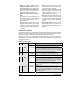
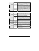
12-Pin Accessories Harness Wire Colour Function (–) Trunk / 1 BLUE 2 BROWN (–) Lock output 3 GREEN (–) Unlock output 4 WHITE / BROWN (–) Rearm output 5 WHITE / GREEN (–) Disarm output 6 BLUE / WHITE (–) AUX 1 output 7 WHITE / ORANGE (–) Starter kill output (armed output) 8 ORANGE (–) AUX 2 output P. 6 AUX 3 output Description 500 mA negative output. This output can be used to control the trunk release (1-sec.
9 PURPLE (–) External Trigger 10 WHITE (–) Ground Out When Running 11 GREY (–) N/A Installation Guide The external trigger wire can be used for remote-starting the vehicle with an external device. When the vehicle is running, triggering this input will activate idle mode. The external trigger wire can also be used to operate as a negative trigger with the trunk pin-switch, the key sense wire or the door pin-switch: Option 1 Connects to negative trunk pin.
In diesel mode, this positive input will monitor the glow plug light: it will wait for up to 30 seconds until the glow-plug light goes out before allowing the module to proceed to cranking the engine. Connect to the side of the glow-plug light which is positive when the light is on. Note: the module will nevertheless proceed to cranking the engine if the glow-plug light is still on after the 30-sec. delay (25 sec. when the run time is set to 30 min.).
2-Pin Harness Wire Colour Function 1 BLUE/ WHITE (–) N/A 2 YELLOW (–) Parking Light output Description This pin is not used. Leave it empty. 500 mA negative parking light output Note: Ensure that the voltage does not vary when the dimmer control switch is turned up or down. If this is the case, it is not the right wire. There is a also a positive parking light output. Only one of these two different outputs needs to be connected.
The Programming Assistance Button (A.k.a. the PAB.) Mounted on the module, this button can be used from within the vehicle instead of the hood pin switch in the engine compartment. This will spare the installer the trouble of accessing the hood pin switch in the engine compartment. Caution: The hood pin switch must be installed and connected in order for the programming assistance button to function. The button will work only when the hood is up.
1. Flash the hood pin switch (see page 9) – The parking lights will stay ON for up to 20 seconds. – Before the lights go out: 2. Press and hold the brake pedal, – And press one of the following buttons on the transmitter: • LOCK to access mode 1; • UNLOCK to access mode 2; • TRUNK to access mode 3; • START/STOP to access mode 4. The parking lights will flash and the horn will honk once (if configured), twice three times or four times to confirm entry into a mode. 3. Release the brake pedal. 4.
Please note that the different functions within any particular mode can only be accessed sequentially: the programming centre will move from function 1 to function 2, then to function 3, and so on. Therefore, whenever you access a particular mode, be prepared to re-configure all the functions of that mode in ascending order. Multi-Level Features (default state) Basic Features (press the FUNCTION button 1X) FUNCTION ¾ FUNCTION ¾ LOCK: .......................................................................
Example: If the multi-level features were set to option 3, the setup would be as follows: x Level 1 Æ Customized feature x Level 2 Æ Multi car operation x Level 3 Æ Basic features The “Basic features” are now programmed as level 3 and therefore: x To access the aux. 2 feature, the user needs to press on the FUNCTION button three (3) times followed by the LOCK button. x To access cold weather mode, the user needs to press on the FUNCTION button three (3) times followed by the START/STOP button.
4. Press the brake pedal and keep it down until you see the parking lights flash 5 times (If the horn is configured, you will hear 1, 2 or 3 honks). 5. Shut down the engine. Tach programming is now complete. Automatic tach programming Tach Adjustments After having programmed the tach you might need to adjust it (increase or decrease the idle speed). In order to do so, you will need to follow these steps: 1- Flash the hood pin (see page 9) 2- Enter the programming centre (see page 10).
Testing Before putting back the vehicle together, it is recommended to check that the system operates properly. The following testing procedures should be used to verify proper installation and operation of the system. Before testing, make sure that all connections are soldered and that the unit is plugged in. Remote-start the engine and listen for starter drag. If the starter cranks for too long, carry out another tach programming procedure. Hood switch shutdown.
Caution! Only one set of pins can be used at one time. Using more than one jumper may result in serious damage to the vehicle. The relay output rating on this unit is 25 A at most. Defective OEM solenoid switches can sometimes draw up to 50 or 60 A, causing the 30 A fuse to blow. Always verify your circuit with an appropriate measuring device.
Priority Door This feature allows to unlock the driver’s door by pressing UNLOCK once and to unlock all other doors by pressing UNLOCK a second time. In order to accomplish this, you must connect the module’s unlock wire to the driver’s door accordingly (i.e.: whatever mechanism that will allow only the driver’s door to unlock when the module’s unlock wire is pulsed). The module’s "priority door access" AUX wire must then connect to the wire in the vehicle that will unlock all doors.
Resetting the module is not a required process. Most of the time, you can avoid resetting by fixing the issue directly at the root of the cause. 1. Flash the hood pin switch (see page 9) – Once inside programming mode, you have 10 seconds to complete the next step. 2. Press and release the break pedal 6 times (within 10 seconds from entering programming mode). 3. The parking lights will flash 8 times to confirm resetting.
Diagnostics – Parking Light Flash Table Flashes 1 2 3 4 5 6 Description • • • • • • • • • • • • • • • • • • • • 8 10 1 – pause – 2 • • • ON solid • • 2 – pause – 2 ON 2 sec. • ON 3 sec. ON 4 sec. • • • ON 25 sec. • Irregular Constant flashes up to 30 sec. Installation Guide Doors locked, starter kill armed. End of run time. TRUNK button pressed Start signal received by the module. Cold weather mode cancelled. Cannot start after maximum number of attempts is reached.
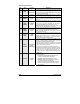
Programming Options MODE 1 * INDICATES DEFAULT SETTING FUNCTION 1 – Ignition-controlled door locks OPTION 1* OPTION 2 OPTION 3 OPTION 4 FUNCTION 4 – Door lock pulse timing Ignition lock DISABLED Ignition lock ENABLED Ignition unlock ONLY Ignition lock ONLY OPTION 1* OPTION 2 OPTION 3 OPTION 4 FUNCTION 2 – Secure lock OPTION 1* OPTION 2 OPTION 3 OPTION 4 OPTION 5 Secure lock DISABLED (1-sec. disarm pulse) Smart secure lock ENABLED in smart mode Secure lock DISABLED (1/2-sec.
AS-2520TW Programming Options and Wiring Diagram