
Specifications

iv
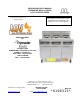
BIELA14 SERIES LOV™
ELECTRIC FRYERS
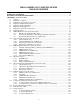
TABLE OF CONTENTS
CAUTIONARY STATEMENTS ..............................................................................................................................i
WARRANTY STATEMENT ...................................................................................................................................ii
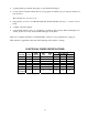
ELECTRICAL POWER SPECIFICATIONS.......................................................................................................iii
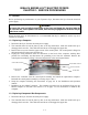
CHAPTER 1: Service Procedures
1.1 General...................................................................................................................................................1-1
1.2 Replacing a Computer............................................................................................................................1-1
1.3 Replacing Component Box Components...............................................................................................1-1
1.4 Replacing a High-Limit Thermostat ......................................................................................................1-3
1.5 Replacing a Temperature Probe.............................................................................................................1-3
1.6 Replacing a Heating Element.................................................................................................................1-5
1.7 Replacing Contactor Box Components..................................................................................................1-6
1.8 Replacing a Frypot.................................................................................................................................1-7
1.9 Built-In Filtration System Service Procedures.......................................................................................1-9
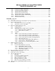
1.9.1 Filtration System Problem Resolution..................................................................................1-9
1.9.2 Replacing the Filter Motor, Filter Pump and Related Components....................................1-10
1.9.3 Replacing the Filter Transformer or Filter Relay................................................................1-12
1.10 ATO (Automatic Top-Off) Service Procedures...................................................................................1-12
1.10.1 ATO Troubleshooting.........................................................................................................1-13
1.10.2 ATO Board Pin Positions and Harnesses............................................................................1-14
1.10.3 Replacing the ATO board or Transformer..........................................................................1-15
1.10.4 Replacing the ATO Pump or Solenoid ...............................................................................1-15
1.11 MIB (Manual Interface Board) Service Procedures.............................................................................1-15
1.11.1 Manually Draining, Refilling or Filtering with the MIB Board..........................................1-16
1.11.2 MIB Troubleshooting .........................................................................................................1-17
1.11.3 MIB Pin Positions and Harnesses.......................................................................................1-18
1.11.4 MIB Display Diagnostics....................................................................................................1-20
1.11.5 MIB Auto Filtration Failure Scenarios ...............................................................................1-22
1.11.6 Replacing the MIB board....................................................................................................1-22
1.12 RTI Service Issues ...............................................................................................................................1-23
1.12.1 RTI MIB Tests....................................................................................................................1-23
1.12.2 RTI LOV Wiring ................................................................................................................1-24
1.12.3 RTI LOV Quick Reference.................................................................................................1-25
1.13 AIF (Automatic Intermittent Filtration) Service Procedures ...............................................................1-26
1.13.1 AIF Troubleshooting...........................................................................................................1-26
1.13.2 AIF Actuator Board Pin Positions and Harnesses ..............................................................1-27
1.13.3 Replacing an AIF Board .....................................................................................................1-28
1.13.4 Replacing an Actuator ........................................................................................................1-28
1.14 M2007 Computer Service Procedures .................................................................................................1-29
1.14.2 M2007 Useful Codes and Passwords..................................................................................1-32
1.14.3 Tech Mode..........................................................................................................................1-33
1.14.4 M2007 Filter Error Flowchart.............................................................................................1-34
1.14.5 M2007 Menu Summary Tree..............................................................................................1-35
1.14.6 M2007 Board Pin Positions and Harnesses ........................................................................1-36
1.15 Loading and Updating Software Procedures........................................................................................1-37
1.15.1 Loading Software from SD card to MIB and AIF boards...................................................1-37
1.15.2 Loading Software from SD card to M2007 Computer or ATO Board ...............................1-38
1.16 Interface Board Diagnostic Chart ........................................................................................................1-39
1.17 Probe Resistance Chart ........................................................................................................................1-40
1.18 Wiring Diagrams..................................................................................................................................1-41
1.18.1 Component Wiring Domestic .............................................................................................1-41
1.18.2 Component Wiring CE .......................................................................................................1-42
1.18.3 Component Wiring CSA.....................................................................................................1-43