
Specifications
1-18
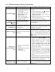
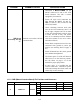
Problem Probable Causes Corrective Action
MIB board
alternating “N” and
“r”.
Network error on the CAN bus
communication.
A. Ensure the CAN bus system is
terminated at BOTH ENDS (on the
M2007 connector J6 and on the ATO
board connector J10) with a resistor
equipped 6-pin connector.
B. Ensure all 6-pin CAN connectors are
tight between the M2007 (J6 and J7),
MIB (J1 and J2), AIF (J4 and J5) and
ATO (J10) boards.
C. Check continuity between each color
wire on the CAN connectors into J7 on
the far right computer and J10 on back
of the ATO board (black to black, white
to white, and red to red), and ensure
there is no continuity between different
color wires (black to red, red to white,
and white to black).
D. Ensure black computer locator wires are
connected from ground to correct pin
position (see drawing 8051734 page 1-
51).
E. Ensure all boards have the corner ground
wire attached and tightened.
F. The locator pin in J2 of the AIF board is
either loose or in the incorrect position.
See the charts on page 1-51 of this
manual for proper pin position.
G. In early units, it is possible that the
resistor could short. Disconnect power
to the unit, unwrap the resistor leads, and
ensure they are not touching.
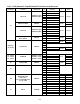
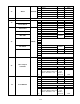
1.11.3 MIB (Manual Interface Board) Pin Positions and Harnesses
Connector From/To Harness # Pin # Function Voltage Wire Color
1 Ground Black
2 CAN Lo Red
3 CAN Hi White
4
5
J1 M2007 J7 8074546
6