
Specifications
1-12
11. When proper operation has been verified, reinstall the back panels and the filter pan and lid.
12. Reposition the fryer under the exhaust hood and reconnect it to the electrical power supply to
return the fryer to service.
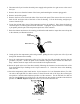
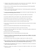
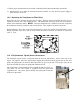
1.9.3 Replacing the Transformer or Filter Relay
Disconnect the fryer from the electrical power supply. Remove the left controller from the fryer to
expose the interior of the left component box. The transformer and relay on the left are located as
shown in the illustration below. NOTE: The right component box is identical to the left except that
the transformer and relay on the left side are not present. Once replaced, reconnect the power.
When replacing a filter relay in the left component box, ensure the 24VDC relay (8074482) is used.
Similar Frymaster fryers use a 24VAC relay, which can lead to confusion. The 24VDC is used in the
LOV™ fryer.
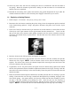
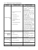
1.10 ATO (Automatic Top-off) Service Procedures
The automatic top-off system is activated when the oil level falls below a sensor in the rear of the
frypot. The signal is sent to the ATO board to engage the solenoid to the frypot and turn on the ATO
pump. The pump draws oil from the JIB (Jug In Box) to a port in the rear of the frypot. Once the oil
level has satisfied the sensor, the pump and solenoid turn off.
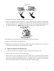
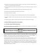
The ATO board is located inside the box, behind the JIB (see Figure 1).
The power for the ATO board is supplied from the right hand
component box. The power passes through the transformer inside the
ATO box to the board.
Figure 1