
Specifications
1-5
12. Secure any loose wires with wire ties, making sure there is no interference with the movement of
the springs. Rotate the elements up and down, making sure that movement is not restricted and
that the wires are not pinched.
13. Reinstall the tilt housing, back panels and contactor plug guards. Reposition the fryer under the
exhaust hood and reconnect it to the electrical power supply to return the fryer to service.
1.6 Replacing a Heating Element
1. Perform steps 1-5 of section 1.5, Replacing a Temperature Probe.
2. Disconnect the wire harness containing the probe wiring, where the temperature probe is attached
to the element being replaced. Using a pin pusher, disconnect the probe wires from the 12-pin
connector.
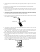
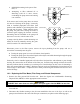
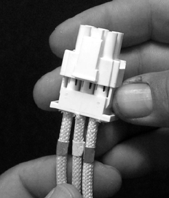
3. In the rear of the fryer disconnect the 6-pin connector for the left element (as viewed from the front
of the fryer) or the 9-pin connector for the right element from the contactor box. Press in on the
tabs on each side of the connector while pulling outward on the free end to extend the connector
and release the element leads (see photo below). Pull the leads out of the connector and out of the
wire sleeving.
4. Raise the element to the full up position and support the elements.
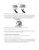
5. Remove the hex head screws and nuts that secure the element to the tube assembly and pull the
element out of the frypot. NOTE: Full-vat elements consist of two dual-vat elements clamped
together. For full-vat units, remove the element clamps before removing the nuts and screws that
secure the element to the tube assembly.
6. If applicable, recover the probe bracket and probe from the element being replaced and install
them on the replacement element. Install the replacement element in the frypot, securing it with the
nuts and screws removed in Step 5 to the tube assembly. Ensure the gasket is between the tube and
element assembly.
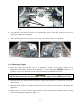
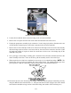
7. Route the element leads through the element tube assembly and into the wire sleeving to prevent
chafing. Ensure that the wire sleeving is routed back through the Heyco bushing, keeping it clear
from the lift springs. Also ensure that the wire sleeving extends into the tube assembly to protect
the edge of the tube assembly from chafing the wires. Press the pins into the connector in
accordance with the diagram on the following page, and then close the connector to lock the leads
in place. NOTE: It is critical that the wires be routed through the sleeving to prevent chafing.