
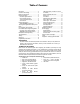
Installation guide


P.4 Installation Guide
vehicle (i.e.: dents, broken glass, damaged
trims, etc.).
♦ Vehicles equipped with daytime running
lights may not allow the installer to view
certain programming results since the daytime
running lights do no go out (Note: The
Parking Light output relay in the Module gives
two “clicks” per flash, 1 click for ON and 1
click for OFF).
♦ Parking Light flashes referred to in this
manual refer to the Parking Light output of the
Module and not that of the vehicle.
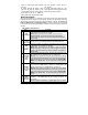
Harness Description
When connecting the Module, it is important to make sure the connector with the Ground wire is
connected first before making the 12-volt connections. Should the unit be powered before being
grounded, there could be serious damage to internal components of the unit. Be careful not to
power up a Module before it is properly grounded. To avoid any accident, it is a recommended
to pull out the fuses from their sockets before the installation, and to put them back during the very
last steps.
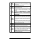
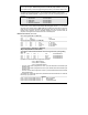
6-Pin Main Ignition Harness
Wire Description
A
RED
+12 V Battery
Connect to the largest 12 V supply wire at the Ignition harness. Ensure that
the OEM power wire is fused for more than 30 A.
NOTE: certain new vehicles have no suitable 12 volts source at the
IGNITION switch (the 12 Volt wire is too small to supply the necessary
current). In this case, the fuse box, or the B+ connection on the battery is
recommended.
B
PURPLE
(+) 30 A
starter output
Connect to the Starter wire of the vehicle (at the IGNITION switch). The source
wire should have +12 V with the Ignition Key in the
CRANK position only.
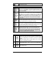
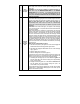
C
RED
(+) 12 V
Battery
Connect to the largest 12 V supply wire at the Ignition harness. Ensure that
the OEM power wire is fused for more than 30 A.
NOTE: certain new vehicles have no suitable 12 volts source at the
IGNITION switch (the 12 Volt wire is too small to supply the necessary
current). In this case, the fuse box, or the B+ connection on the battery is
recommended.
D
YELLOW
(+) 30 A
ignition
output
Connect to Ignition wire of the vehicle. The source wire should have +12 V
with the Ignition Key in the
IGNITION ON (RUN) and CRANK positions.
Warning: some vehicles have more than one IGN wire at the IGNITION
switch for powering the heater blower motor. Use the 5th relay (pin F) and
extra relays to power up any extra IGN. wires if necessary. DO NOT JUMP
WIRES at the IGNITION switch, this will compromise the OEM electrical
system.
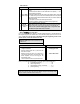
E
ORANGE
(+) 30 A
Accessories
output
This wire is for powering the heater blower motor. It is usually classed as an
ACC. (no power in the CRANK position.) if it tests as an IGNITION (power in the
crank pos.) then power it as an
IGNITION (5th relay, or extra fuse).
Warning: some vehicles have more than one ACC wire at the IGNITION
switch for powering the heater blower motor. Use the 5th relay (pin F) and
extra relays to power up any extra ACC. wires if necessary. DO NOT JUMP
WIRES at the IGNITION switch, this will compromise the OEM electrical
system.
F
GREEN
(+) 30 A 5
th
relay output
This high-current output can be used to power a 2
nd
IGNITION or a 2
nd
ACCESSORY or a 2
nd
STARTER WIRE. See jumper settings on page 14 for
correct output.
Additional IGNITIONS, ACCESSORIES, or STARTER WIRES must use external