AUTOMATIC TRANSMISSION REMOTE STARTER AND FULL ALARM SYSTEM Installation Guide W A R N I N G ! This is a generic installation guide and it is designed for the specific model number stated above. Furthermore, for clarity purposes, the START/STOP button, associated with 4button models, will be referred to as either START or STOP depending on the functionality being described.
Table of Contents Introduction ..................................................... 2 Included in the Package ................................. 2 Before You Get Started…............................... 3 Harness Description ....................................... 4 6-Pin Main Ignition Harness ....................... 4 5-Pin Secondary Harness........................... 5 12-Pin Accessories Harness ...................... 5 2-Pin Harness ............................................. 8 Flashing the Hood Pin ...
INDUSTRY CANADA USER NOTICE (Canada): Operation is subject to the following two conditions: (1) this device may not cause interference, and (2) this device must accept any interference, including interference that may cause undesired operation of the device. To reduce potential radio interference to other users, the antenna type and its gain should be so chosen that the equivalent isotropically radiated power (EIRP) is not more than that required for successful communication". FCC USER NOTICE (U.S.A.
vehicle (i.e.: dents, broken glass, damaged trims, etc.). ♦ Vehicles equipped with daytime running lights may not allow the installer to view certain programming results since the daytime running lights do no go out (Note: The Parking Light output relay in the Module gives two “clicks” per flash, 1 click for ON and 1 click for OFF). ♦ Parking Light flashes referred to in this manual refer to the Parking Light output of the Module and not that of the vehicle.
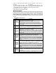
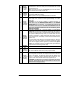
relays. DO NOT JUMP WIRES at the IGNITION switch, this will compromise the OEM electrical system. 5-Pin Secondary Harness Wire Description 1 BLACK (–) Chassis ground input 2 PURPLE (AC) Tachometer input This wire must be connected to bare, unpainted metal (the Chassis or true Body ground). It is preferable to use a factory ground bolt rather than a selftapping screw. Screws tend to get loose or rusted over time and can cause erratic problems.
4 WHITE / BROWN (–) Arm output 500 mA ground output when the LOCK button is pressed. This output is activated 500 ms before the LOCK pulse and deactivated 250 ms after the LOCK pulse ends. Note: The system will also give an ARM/REARM pulse on this wire when it shuts down the vehicle after a remote start. 5 WHITE / GREEN (–) Disarm output 500 mA ground output when the UNLOCK button is pressed. This wire is for disarming OEM Alarm systems. Note: System will also give a DISARM pulse before remote start.
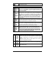
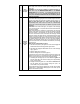
11 GRAY (–) Negative Door input 12 YELLOW (+) Glowplug Light input Installation Guide This input should be used in vehicles that use a negative-switching Dome Light circuit. Connect to a Dome Light wire testing ground with a Door open. CAUTION! You can only use a negative or a positive connection. In other words, only the NEGATIVE DOOR INPUT or the POSITIVE DOOR INPUT wire is connected.
2-Pin Harness Wire Description • 500 mA negative output. Can be programmed for one of the following options: • Constant while the SHIFT and then LOCK buttons are pressed, + 1 sec. after the buttons are released. BLUE / WHITE • Pressing the SHIFT and then LOCK buttons will toggle the AUX 2 output ON 1 ( -) AUX 2 output for a 30-second cycle and shuts off automatically unless the user presses SHIFT and then LOCK buttons before the end of that cycle, at which point, the AUX2 output shuts off.
The Programming Assistance Button (A.k.a. PAB.) The PAB is located on the side of the Module. This push button mimics the Hood-Pin switch in order to avoid having to get out of the vehicle and pressing the Hood-Pin switch. The PAB will work only when the Hood is up. How to Program the Transmitter. 1. FLASH the Hood Pin Switch. Before the 20 seconds have passed, turn the Ignition Key to the IGNITION ON (RUN) position. Turn the IGNITION to OFF. 2.
Note: The unit will stay in the selected programming mode until the hood pin-switch or the brake pedal is pressed again. Therefore take your time to make the proper selection. Pressing the brake pedal will take you back to the programming centre, where you can select a different mode. Once you access a particular programming mode, you will automatically start at function 1. Once you select one of the options of function 1, you will automatically be taken to the next function.
Option 2: Basic features Level 1 (requires pressing the SHIFT button 1X) Æ Level 2 (requires pressing the SHIFT button 2X) Æ Multi car operation Level 3 (requires pressing the SHIFT button 3X) Æ Customized features Option 3: Customized features Level 1 (requires pressing the SHIFT button 1X) Æ Level 2 (requires pressing the SHIFT button 2X) Æ Multi car operation Level 3 (requires pressing the SHIFT button 3X) Æ Basic features Option 4: Level 1 (requires pressing the SHIFT button 1X) Æ Basic features Level 2
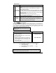
2. With the hood up (ground on the hood pin line), start the vehicle using the key. 3. Let the engine reach proper idle speed The parking light output from the module is activated when the vehicle starts and it will shut off once the tach signal is detected. 4. Press and hold the brake pedal until the parking light output from the module flashes 5 times. 5. Turn the Ignition OFF. At this point, the tach setting has been programmed. Table 4 Multi-Speed Tach Programming No manual adjustments are necessary.
3. 4. 5. 6. 7. • • • • • 8. 9. 10. 11. Test the Brake shutdown circuit: With the vehicle running under the Remote Starter, press and release the Brake Pedal. The Engine should shut down immediately. If the Engine continues to run, check the Brake Switch connection. OEM Alarm Control: Make sure the Module is able to arm and disarm the OEM Alarm (if applicable). Alarm Testing: Arm the vehicle and test the Hood Pin and each Door to make sure that each one of these points triggers the Alarm.
Supplementary Information Fifth Relay Output (2nd IGN or 2nd ACC or 2nd START) This Remote Starter is equipped with a high-current programmable 5th relay onboard that can be used to power a second Ignition, Accessory, or Start wire. The Unit uses a series of jumpers; each set of jumper pins represents a function.
• If the Alarm is armed and the Starter Kill is armed, a remote start signal will be accompanied by an UNLOCK and a DISARM pulse preceding start-up. The system will LOCK and arm again once the Engine is running. • If the Vehicle is initially unlocked, a remote start signal will start the Engine and enable the Starter Kill without unlocking or locking the Doors. Table 8 Turbo Mode This Option allows turbochargers to idle down: after the user leaves the vehicle, the Engine will keep running for 60 sec.
Option 1: Active Mode: the system will not arm automatically. Press LOCK to arm and UNLOCK to disarm the system. Option 2: Passive Mode: the system will arm itself unless remote-armed within 30 sec. Press UNLOCK to disarm. Option 3: Passive Mode without Two-Stage Disarm: Press UNLOCK to disarm. Option 4: Active Mode with Disarmed Notification.
The system will play back the most recent event first, then the second most-recent, and so on. If there are no events at all to report, the Parking Lights will give one long flash.
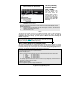
Diagnostics - Parking Lights Flash Rate Flashes 1 2 3 4 5 6 8 10 1 – pause – 2 2 – pause – 2 ON solid ON 2 sec. ON 3 sec. ON 4 sec. ON 25 sec. Irregular • • • • • • • • • • • • • • • • • • • • • • • • • • • • • • • Constant flashes • up to 30 sec. P.18 Description Doors locked, Starter Kill armed. End of Run Time. TRUNK button pressed START signal received by the Module. Cold Weather Mode cancelled. Cannot start after maximum number of attempts is reached. Run Time cancelled.
Programming Options Mode 1 *indicates default setting Function 1 – Ignition-Controlled Door locks OPTION 1* Ignition Lock disabled OPTION 2 Ignition lock enabled OPTION 3 Ignition unlock only OPTION 4 Ignition lock only Function 2 – Secure Lock OPTION 1* Secure Lock disabled (1-sec. disarm pulse.) OPTION 2 Secure Lock enabled in smart mode. OPTION 3 Secure Lock disabled (0.5 Sec disarm pulse) OPTION 4 Secure Lock enabled in normal mode.
AS-6320FM PROGRAMMING OPTIONS AND WIRING DIAGRAM